Follow-up mulch reeling recycler
A follow-up, recycling machine technology, applied in the field of agricultural machinery, can solve problems such as difficult practical application and complex structure, and achieve the effect of simple structure and low cost.
- Summary
- Abstract
- Description
- Claims
- Application Information
AI Technical Summary
Problems solved by technology
Method used
Image
Examples
Embodiment 1
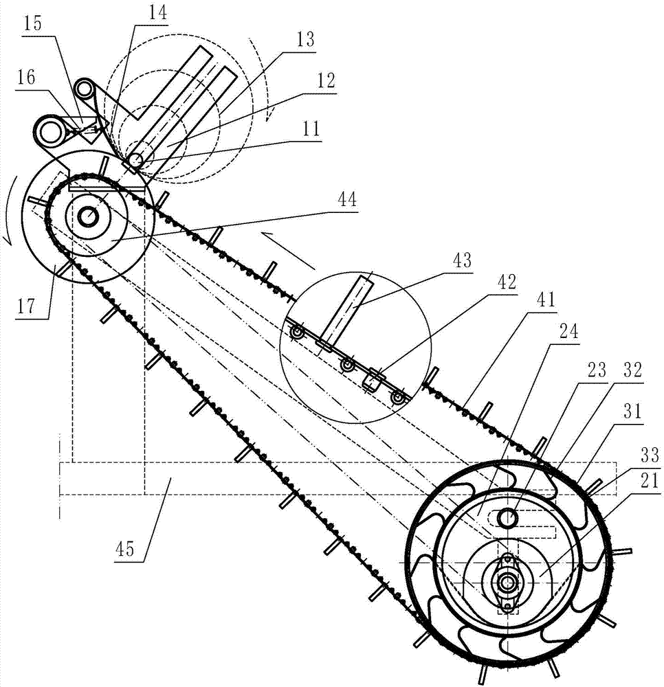
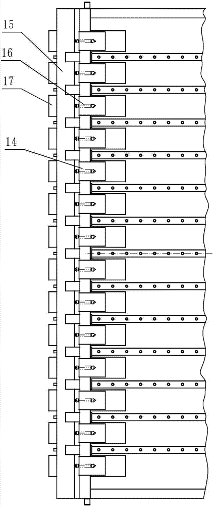
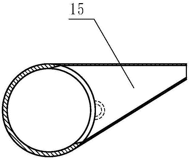
[0046] Embodiment 1: refer to Figure 1-13 , is a structural schematic diagram of Embodiment 1 of the present invention, including a frame 45, a transmission mechanism, and a belt-type film-removing mechanism, and the belt-type film-removing mechanism includes a spike-tooth pick-up belt 41, a main drive roller 44 and a driven roller, and the spike-tooth The pick-up belt 41 is several two side-by-side ring-shaped belts, and the ring-shaped belts are provided with regularly arranged finger-like spikes 43, and the finger-like spikes 43 on the side-by-side ring-shaped belts form finger-like nails. Tooth matrix, on the main drive drum 44 between the endless belt-shaped bodies is provided with stripping wheel set, this stripping wheel set is made up of several stripping wheels 17 juxtaposed, and described stripping wheel 17 diameters are greater than or equal to main The finger-shaped nail teeth 43 upper ends at the driving drum 44 places form a circle with the main driving drum 44 ...
Embodiment 2
[0053] Embodiment 2: refer to Figure 14 with 17 , is a schematic structural view of Embodiment 2 of the present invention. Compared with Embodiment 1, the difference of this embodiment is that the spike-tooth pick-up belt track 33 is a strip-shaped annular body in the circumferential direction of the surface of the driven roller body 34, An annular groove A37 and a concave hole A36 are provided on the bar-shaped annular body, and the main driving roller 44 is provided with an annular groove B46 and a concave hole B47 on the previous stage.
Embodiment 3
[0054] Embodiment 3: refer to Figure 15-17 , is a structural schematic diagram of Embodiment 3 of the present invention. Compared with Embodiments 1 and 2, the difference of this embodiment is that: the roller set 26 is arranged at both ends of the driven roller body 34, and the ring-shaped track-shaped body 31 Set on the two fixed plates A25, the roller set 26 is located on the inner or outer edge of the annular track-shaped body 31, so that the driven roller body 34 can rotate on the roller set 26, and the mixed groove 32 The inner side is provided with reinforcing ribs 35 . In this embodiment, the stripping wheel 17 is a hollow wheel, and the main driving roller 44 is provided with an annular groove B46 and a concave hole B47 on the upper stage.
PUM
 Abstract
Description
Claims
Application Information
 - R&D
- Intellectual Property
- Life Sciences
- Materials
- Tech Scout
- Unparalleled Data Quality
- Higher Quality Content
- 60% Fewer Hallucinations
Browse by: Latest US Patents, China's latest patents, Technical Efficacy Thesaurus, Application Domain, Technology Topic, Popular Technical Reports.
© 2025 PatSnap. All rights reserved.Legal|Privacy policy|Modern Slavery Act Transparency Statement|Sitemap|About US| Contact US: help@patsnap.com


