Microfluidic chip capable of realizing high-efficiency mixing

A microfluidic chip and fluid technology, applied in mixers, fluid mixers, laboratory containers, etc., can solve the problems of long mixing time, poor mixing quality, uneven mixing, etc., to achieve fully efficient mixing, fast mixing, etc. mixed effect

Inactive Publication Date: 2017-11-24
QINGDAO UNIV OF SCI & TECH
View PDF11 Cites 5 Cited by
  • Summary
  • Abstract
  • Description
  • Claims
  • Application Information

AI Technical Summary

Problems solved by technology

Although the above technical solution realizes the micro-mixing of two or more components, it has disadvantages such as uneven mixing, long mixing time, and poor mixing quality.

Method used


Image

  • Microfluidic chip capable of realizing high-efficiency mixing
  • Microfluidic chip capable of realizing high-efficiency mixing
  • Microfluidic chip capable of realizing high-efficiency mixing

Examples


Embodiment 1

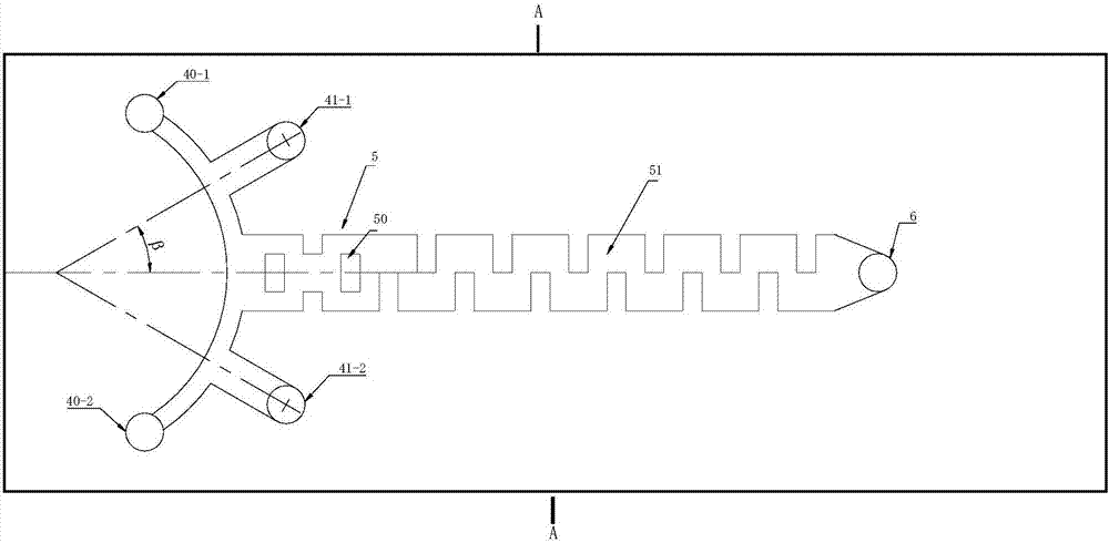
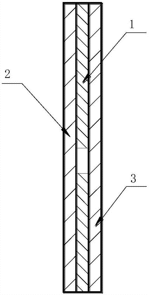
[0025] Such as figure 1 , 2 As shown, a microfluidic chip that can realize efficient mixing includes a substrate 1, an upper glass sheet 2 and a lower glass sheet 3 covering the upper and lower sides of the substrate, the substrate 1 is provided with channels of different geometric structures, and the channels include Inlet channel 4 , straight channel 5 and outlet channel 6 ; said channels are evenly distributed on substrate 1 . The inlet passage 4 is symmetrical about the central axis of the substrate 1, and an arc channel is provided at one end of the substrate 1 as the inlet channels 40-1 and 40-2 of the fluid A; the radially outward extension of the arc channel is provided with The inlet channels 41-1, 41-2 for fluid B, and the channels for fluid A and B form a crown shape. The front section of the straight channel 5 is inlaid with inserts 50 near the entrance channel, and the middle and rear sections of the straight channel 5 are concave-convex channels 51 that are eve...

Embodiment 2

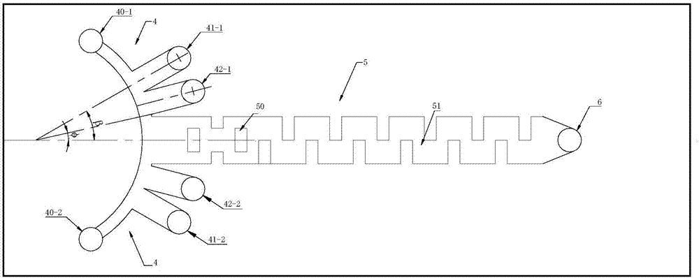
[0027] Such as image 3 As shown, the difference from Embodiment 1 is that the inlet passages 42-1, 42-2 of fluid C are also provided at the radially outward extension of the arc passage, the passages of fluid B and C are next to each other, and the inlet passage of fluid C is connected to the straight passage 5 Adjacent, the fluid A channel forms a crown shape with the fluid B and C channels. The angle β between the central axis of the inlet channel of fluid B and the central axis of the straight channel ranges from 15° to 75°, and the angle φ between the side of the inlet channel of fluid C near the straight channel and the central axis of the straight channel ranges from 10° to 35°. In this embodiment, the runners B and C are next to each other, and the runners B and C can also be connected by an arc channel, and the positions of the two can also be interchanged, and the layout is not limited to this embodiment.

Embodiment 3

[0029] Such as Figure 4 As shown, a microfluidic chip that can realize efficient mixing includes a substrate 1, an upper glass sheet 2 and a lower glass sheet 3 covering the upper and lower sides of the substrate, the substrate 1 is provided with channels of different geometric structures, and the channels include Inlet channel 4 , straight channel 5 and outlet channel 6 ; said channels are evenly distributed on substrate 1 . The inlet channel 4 is located on one side of the substrate, and an arc channel is provided at one end of the substrate 1 as an inlet channel 40-1 of fluid A; an inlet channel of fluid B is provided at the radially outward extension of the arc channel 41-1, the channels of fluid A and B form a half crown shape. The inner side of the circular arc channel, that is, the side with a small radius, is the arc tangent line instead of the arc at the confluence with the straight channel. The front section of the straight channel 5 is inlaid with inserts 50 near...


PUM


Abstract

The invention discloses a microfluidic chip capable of realizing high-efficiency mixing. The microfluidic chip comprises a substrate as well as an upper glass sheet and a lower glass sheet which are covered on the top and bottom of the substrate, wherein channels with different geometrical structures are arranged on the substrate; the channels comprise an inlet channel, a straight channel and an outlet channel; all the channels are uniformly distributed on the substrate. The microfluidic chip capable of realizing the high-efficiency mixing, disclosed by the invention, has the beneficial effects that uniformity stress of the microfluidic chip is facilitated, the service life of the substrate is prolonged and measurement errors caused by the deformation of the substrate are reduced; high-efficiency and rapid mixing of different components can be realized and a uniformly-mixed solution is obtained.

Description

technical field [0001] The invention belongs to the technical field of mixing macromolecules and biological fluids at a microscale, and in particular relates to a microfluidic chip capable of achieving high-efficiency mixing. Background technique [0002] At present, although traditional microfluidic chips are widely used, most microfluidic biochips and MEMS have been used in biological and medical research, as well as the control of Lab-on-chip. However, most of them are only used for the delivery and control of single-component microfluids. For the mixing of two or more fluids, there are still disadvantages of low mixing efficiency and long time, which cannot meet the needs of scientific experiments that require rapid mixing of multiple microfluids. [0003] In the Chinese patent literature, the invention patent with the publication number CN102527280A and the invention title "a micro-mixing and micro-reaction device" discloses a technical solution, including a microfluidi...

Claims


Application Information

Patent Timeline
Patent Type & Authority Applications(China)
IPC IPC(8): B01F13/00B01F5/00B01L3/00
CPCB01L3/5027B01L2300/0867B01L2200/027B01F25/00B01F33/30
Inventor 王伟王安迎孙熙林
Owner QINGDAO UNIV OF SCI & TECH
Why Eureka
Try Eureka