Contact-type central water-discharging permanent magnet synchronous electric spindle

A central water outlet and permanent magnet synchronization technology, which is applied to large fixed members, metal processing machinery parts, maintenance and safety accessories, etc., can solve problems such as tool cooling, improve processing quality, power and torque, and improve tool cooling effect Effect

Active Publication Date: 2017-11-24
GUANGZHOU HAOZHI ELECTROMECHANICAL
View PDF7 Cites 7 Cited by
  • Summary
  • Abstract
  • Description
  • Claims
  • Application Information

AI Technical Summary

Problems solved by technology

[0005] In order to overcome the deficiencies of the prior art, the first object of the present invention is to provide a contact type central water outlet permanent magnet syn

Method used


Image

  • Contact-type central water-discharging permanent magnet synchronous electric spindle
  • Contact-type central water-discharging permanent magnet synchronous electric spindle
  • Contact-type central water-discharging permanent magnet synchronous electric spindle

Examples


Embodiment 1

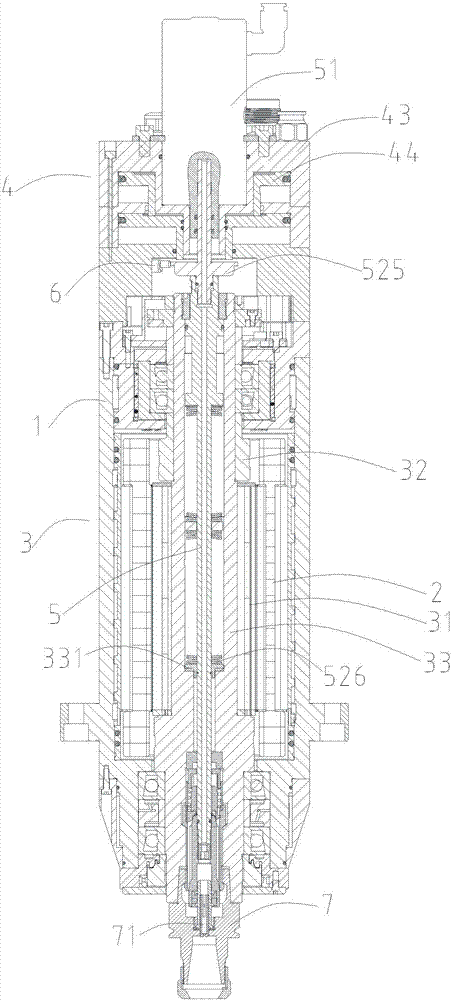
[0033] refer to figure 1 , a contact type central water outlet permanent magnet synchronous electric spindle, comprising a body 1, a stator 2, a permanent magnet shaft core assembly 3, a cylinder assembly 4, a central water outlet assembly 5 and a sensor 6;

[0034] The stator 2 and the permanent magnet shaft core assembly 3 are both arranged in the inner cavity of the body 1; the permanent magnet shaft core assembly 3 includes a permanent magnet rotor 31, an interaxial sleeve 32 and a shaft core 33; the permanent magnet rotor 31 is sleeved with a shaft core 33; The shaft sleeve 32 is arranged above the permanent magnet rotor 31;

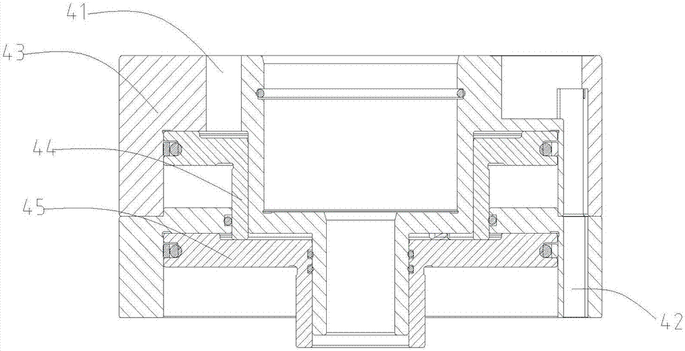
[0035] refer to figure 2 , the cylinder assembly 4 is arranged on the upper end of the body 1; the cylinder assembly 4 includes a first air passage 41, a second air passage 42, a cylinder top cover 43, a first piston 44 and a second piston 45; the cylinder top cover 43, the first piston 44 and the second piston 45 are pressed sequentially from to...

Embodiment 2

[0059] This embodiment is characterized in that: with reference to Figure 4 , A glue layer 34 is provided between the lower end surface of the permanent magnet rotor 31 and the shaft core 33; a gap 35 is provided between the interaxial sleeve 32 and the permanent magnet rotor 31; the rest of the structures and features are the same as those in Embodiment 1.

[0060] Since the permanent magnet rotor is magnetic, it will attract iron filings on the shaft core, especially embedded in the gap between the shaft sleeve and the permanent magnet rotor, which is difficult to remove. If the iron filings cannot be removed, the high-speed rotation of the spindle will throw the iron filings out, resulting in a shortened service life of the electric spindle. In order to solve this problem, the lower end surface of the permanent magnet rotor is glued and then installed on the shaft core to form a glue layer to prevent the embedding of iron filings; a 1mm gap is designed between the permanen...


PUM


Abstract

The invention discloses a contact-type central water-discharging permanent magnet synchronous electric spindle. The contact-type central water-discharging permanent magnet synchronous electric spindle comprises a machine body, a stator, a permanent magnet spindle core assembly, an air cylinder assembly and a central water-discharging assembly; the permanent magnet spindle core assembly comprises a permanent magnet rotor, a between-spindle sleeve and a spindle core, the permanent magnet rotor is arranged on the spindle core in a sleeving mode, and the spindle space sleeve is arranged above the permanent magnet rotor; the air cylinder assembly is arranged at the upper end of the machine body and comprises a first air duct, a second air duct, an air cylinder top cover, a first piston and a second piston, the air cylinder top cover, and the first piston and the second piston sequentially abut against from top to bottom in the central axial direction of the electric spindle; the central water-discharging assembly comprises a rotary connector, a connecting rod, a pulling rod, a sliding core and a pulling claw which are sequentially connected from top to bottom, the pulling claw is arranged on the lower end portion of the sliding core in a sleeving mode, the pull claw and the sliding core slide oppositely so that the pull claw can switch under the stretching and retracting states. According to the contact-type central water-discharging permanent magnet synchronous electric spindle, central water discharging is achieved, the cooling problem and the difficult problem of chip removing of tools in the ceramic processing and deep hole processing are solved.

Description

technical field [0001] The invention relates to a contact type central water outlet permanent magnet synchronous electric spindle, which belongs to the field of electromechanical technology. Background technique [0002] The electric spindle integrates the machine tool spindle and the spindle motor, and is driven by its own motor and an external frequency converter or driver. The electric spindle is widely used in high-end machine tools because of its convenient installation, compact structure, light weight, small vibration, high speed, high machining accuracy, and stable machining effect. At present, the electric spindles used in China are basically driven by asynchronous motors. The inherent shortcomings of asynchronous motors limit the further development of asynchronous electric spindles. The disadvantages of asynchronous motors are mainly manifested in the serious heating of the motor, low power factor, low power density, and poor overload capacity. The permanent mag...

Claims


Application Information

Patent Timeline
IPC IPC(8): B23B19/02B23Q11/10
CPCB23Q1/70B23Q11/1023Y02P70/10
Inventor 汤秀清魏雷宝
Owner GUANGZHOU HAOZHI ELECTROMECHANICAL
Why Eureka
Try Eureka