
Magnetic attraction type damping fin magnetizing and punching device and production technology thereof

A production process and damping sheet technology, which is applied in the field of automobile damping, can solve the problems of short service life of conveyor belts, poor effective service life, and high cost of substitutes, and achieve the effects of improving efficiency, reducing harmful gases, and good viscoelastic performance

Active Publication Date: 2017-11-24
MAANSHAN LIANHONG SYNTHETIC MATERIALS
View PDF6 Cites 3 Cited by
  • Summary
  • Abstract
  • Description
  • Claims
  • Application Information

AI Technical Summary

Problems solved by technology

[0007] Aiming at the problems existing in the prior art that although the cost of the asphalt damping plate is low, there are many harmful gases, the cost of the substitute is high, the effective service life is poor, the dehydration is not timely, the burrs are serious during cutting, and the service life of the conveyor belt is short, the present invention provides A magnetizing and punching device for a magnetic-absorbing damping sheet and its production process

Method used


Image

  • Magnetic attraction type damping fin magnetizing and punching device and production technology thereof
  • Magnetic attraction type damping fin magnetizing and punching device and production technology thereof
  • Magnetic attraction type damping fin magnetizing and punching device and production technology thereof

Examples


Embodiment 1

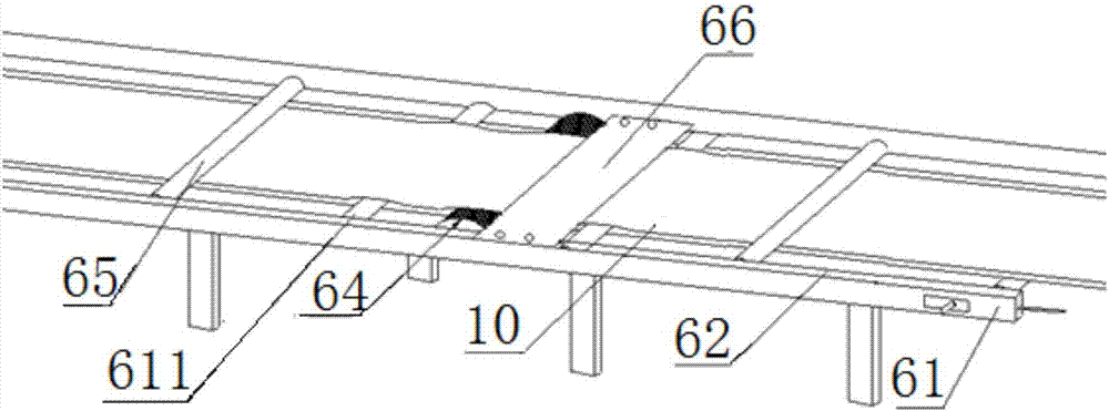
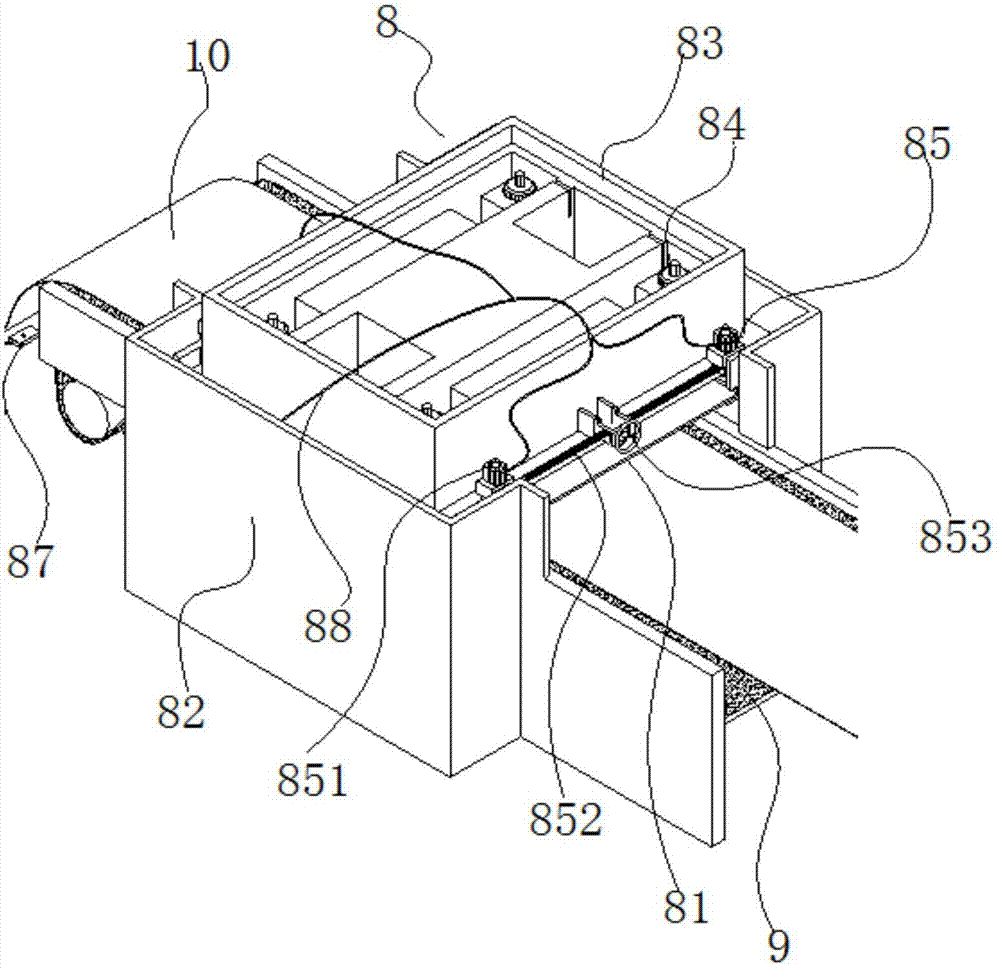
[0063] The magnetizing and punching device of the magnetic suction type damping plate in this embodiment includes a magnetizing mechanism 6 and a stamping and cutting mechanism 8 arranged in a process; wherein: as figure 1 As shown, the magnetizing mechanism 6 includes a magnetizing frame 61, a magnetizing conveyor belt 62, a magnetizing roller 64 and a pressing plate 66, and the magnetizing conveyor belt 62 is reciprocatingly laid on the surface of the magnetizing frame 61; The two ends of the roller 64 are detachably and fixedly connected with the magnetizing frame 61, and are suspended above the magnetizing conveyor belt 62; Magnetic roller 64, and reserve the gap that magnetic suction type damping sheet 10 can pass through, pressing plate 66 can squeeze and dehydrate the cooling water on the surface of magnetic suction type damping sheet, lay the foundation for the surface water absorption and drying of the next step; as figure 2 As shown, the stamping and cutting mechani...

Embodiment 2

[0083] The basic structure and ingredients of the magnetizing and punching device for the magnetic damping sheet in this embodiment are the same as those in Embodiment 1. The difference and improvement lies in that there are two pressing plates 66, and the two sides of the magnetizing roller 64 are in the shape of " Eight "shaped obliquely symmetrical settings, double-sided water pressure, improve efficiency; the lifting height adjustment mechanism 84 is 4 lifting screws symmetrically arranged at the four corners of the stamping table 83, and the lifting can be adjusted in a balanced manner at the four corners to ensure punching. The balance of the cutting surface; the bottom of the front end of the die-cutting conveyor belt 9 is provided with a damping sheet induction mechanism 87, and when no damping sheet passes through, the control mechanism can be notified to stop punching, so as to avoid damage to the conveyor belt by die cutting.

[0084] The production process of the ma...

Embodiment 3

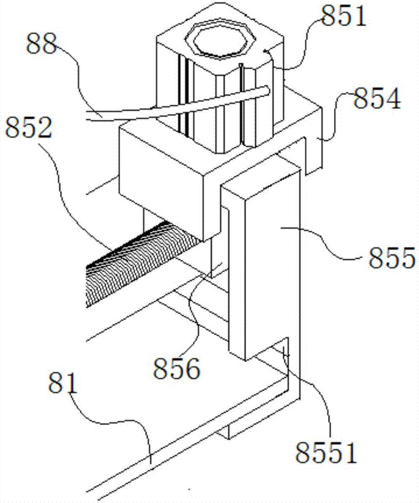
[0103] The basic structure and ingredients of the magnetizing and punching device for the magnetic suction type damping sheet in this embodiment are the same as those in Embodiment 2. The difference and improvement are that the punching and cutting mechanism 8 also includes , the 2 die width adjustment mechanisms 85 directly above the punching conveyor belt 9 are adjusted accordingly according to the die specifications to improve the versatility of the device; Fixed on the magnetizing frame 61, symmetrically arranged on the magnetizing conveyor belt 62, and a gap is reserved between the magnetizing conveyor belt 62; the bottom of the magnetizing conveyor belt 62 is also provided with an idler 611, which cooperates with the pressing plate 66 to squeeze out Moisture blots dry.

[0104] The component of step one batching comprises the magnetic powder of 350 kilograms, the superfine light calcium powder of 250 kilograms particle diameter 0.5~1 μ m; Ethylene-vinyl acetate copolyme...


PUM

PropertyMeasurementUnit
Particle sizeaaaaaaaaaa
Tear strengthaaaaaaaaaa

Abstract

The invention discloses a magnetic attraction type damping fin magnetizing and punching device and a production technology thereof, and belongs to the technical field of automobile damping. The magnetic attraction type damping fin magnetizing and punching device comprises a magnetizing mechanism and a punching and cutting mechanism which are arranged according to working procedures, wherein the magnetizing mechanism comprises a magnetizing frame, a magnetizing conveyor belt, a magnetizing roller and a pressing plate; the two ends of the magnetizing roller are detachably and fixedly connected with the magnetizing frame; the two side ends of the pressing plate are detachably and fixedly connected with the magnetizing frame; the punching and cutting mechanism comprises two supporting tables for punching the two sides of the conveyor belt, a punching table and a lifting type height adjusting mechanism which are flatly placed and fixed to the inner side faces of the two supporting tables and a punching conveyor belt penetrating through the punching and cutting mechanism to convey magnetic attraction type damping fins. The problems that even though an asphalt type damping plate is low in cost, more harmful gas is produced, the substitute cost is high, the effective service life is short, dehydration is not performed in time, multiple burrs are formed during cutting, and the service life of the conveyor belt is short are solved.

Description

technical field [0001] The invention relates to the technical field of automobile damping, in particular to a magnetizing and punching device for a magnetically attracted damping sheet and a production process thereof. Background technique [0002] Vibration damping materials are widely used in automotive applications to attenuate road noise and engine vibration and sound. For damping materials, viscoelastic materials are preferred. The damping effect associated with the energy dissipated in a viscoelastic material increases with Young's modulus, as well as the loss factor of the viscoelastic material. Of course, it also increases with the deformation the material is subjected to. Some materials have a high loss tangent but a low Young's modulus, which provide limited damping to the metal plate, and other materials have a high Young's modulus but a low loss tangent (e.g., rubber), which also acts as a damping component and does not Not very good. A good damping material ...

Claims


Application Information

Patent Timeline
IPC IPC(8): B26F1/38B26F1/44B26D7/26H01F13/00C08L95/00C08L97/02C08K13/02C08K3/34C08K3/26
CPCH01F13/003C08L95/00B26D7/2628B26F1/38B26F1/44C08L2205/16C08K2003/265C08L97/02C08K13/02C08K3/34C08K3/26
Inventor 刘福潘乐窦正平傅昌宏
Owner MAANSHAN LIANHONG SYNTHETIC MATERIALS
Learn More