

Self-inducing magnetic resistance type electromagnetic damper
An electromagnetic damper and reluctance type technology, applied in the direction of shock absorber, magnetic spring, spring/shock absorber, etc., can solve the problems of poor engineering applicability and small damping force, and achieve good anti-swing and anti-swing Effects of impact performance, improvement of output characteristics, and optimized structure
- Summary
- Abstract
- Description
- Claims
- Application Information
AI Technical Summary
Problems solved by technology
Method used
Image

Examples
Embodiment Construction
[0019] The present invention will be described in detail below with reference to the accompanying drawings and examples.
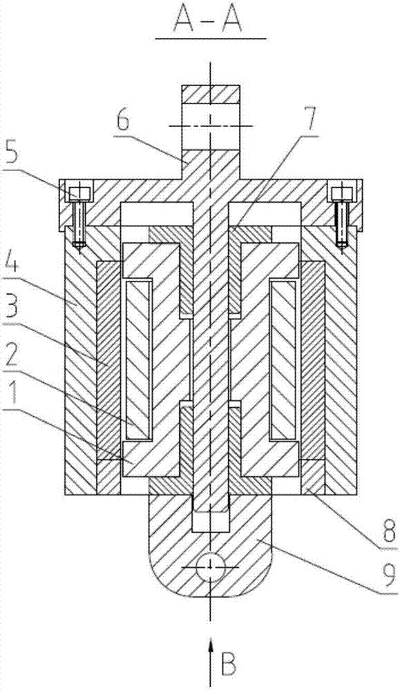
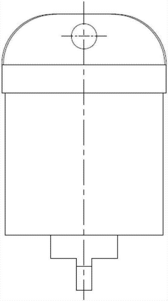
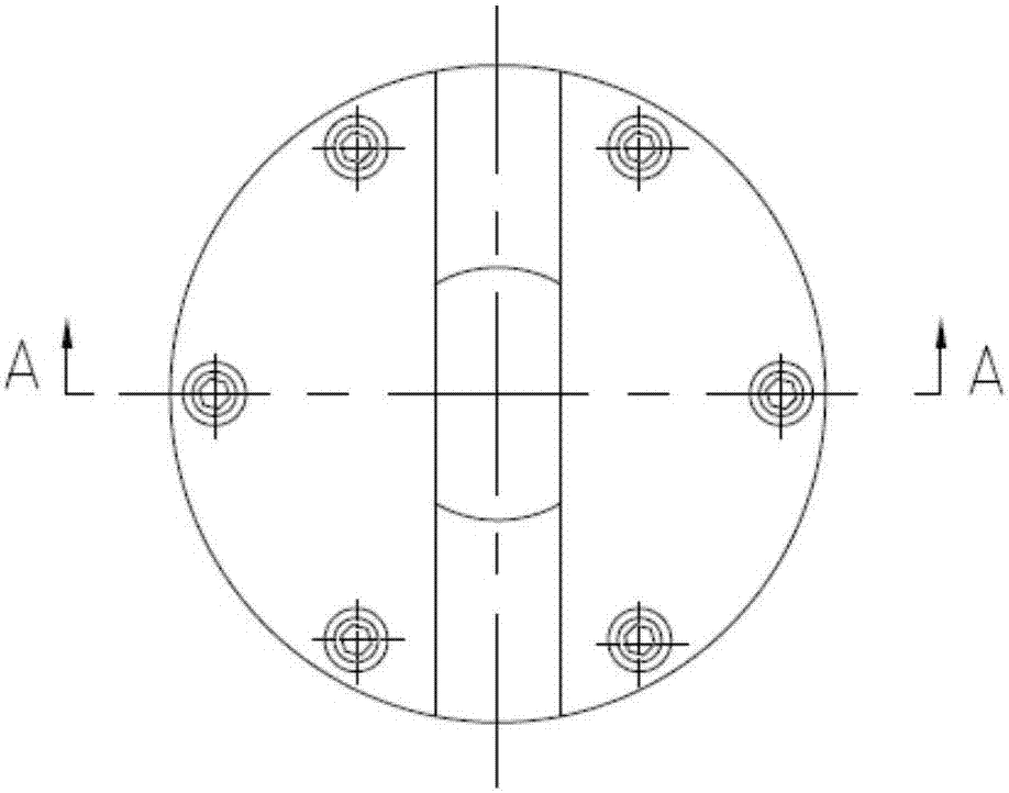
[0020] as attached Figure 1-4 As shown, the present invention provides a self-inductive reluctance type electromagnetic damper, the damper includes a casing stator assembly and an internal mover assembly, the casing stator assembly consists of an annular permanent magnet 3, a permanent magnet upper yoke 4, fastening bolts 5. The upper bracket 6 is composed of the permanent magnet lower yoke 8; the internal mover assembly is composed of a soft magnetic metal yoke 1, a coil 2, a lower bracket 9 and two linear bearings 7;
[0021] The upper yoke 4 of the permanent magnet and the lower yoke 8 of the permanent magnet are combined to form an annular cavity for installing the annular permanent magnet 3. The annular permanent magnet 3 is installed in the annular cavity. The upper bracket 6 has a circular end cover, and the end There is a guide shaft in the cente...
PUM
 Abstract
Description
Claims
Application Information