Hot wall type heat exchanger
A heat exchanger and heat exchange fluid technology, applied in indirect heat exchangers, lighting and heating equipment, etc., can solve problems such as limitations in the application field of heat exchangers, and achieve easy design optimization, faster cycle speed, and improved heat exchange efficiency. Effect
Pending Publication Date: 2017-11-24
HUNAN CHUANGHUA LOW CARBON ENVIRONMENTAL PROTECTION TECH
0 Cites 34 Cited by
AI-Extracted Technical Summary
Problems solved by technology
[0008] The main purpose of the present invention is to provide a hot-wall heat exchanger, aiming t...
View moreMethod used
As can be seen, since the heat wall 1 adopts the thinning heat exchange partition 5 to reduce the cost and improve the heat exchange efficiency, the support force needs to be strengthened between the heat wall 1, and various forms of channel support bars and stress-resistant rectangular The fins 16, on the one hand, can improve the strength of bearing fluid pressure, and on the other hand, can expand the heat exchange area in a limited volume. It can be placed between the rectangular hot walls 1, and there is also a channel support bar as shown in Figure 6. There are fins 16 in the channel of the channel bar 6, which can be inserted into the hot wall 1 one by one, and can also be pulled out one by one. cleaning. And the inner supporting device 2 in the hot wall 1 is shown in Figure 2 and Figure 4, and it is similar to the rectangular fin 16, just has through hole up and down of the fin 16, facilitates the phase change fluid in the hot wall 1 to flow horizontally from side to side, when When the hot wall 1 is used as a heat-absorbing element, the evaporation of the phase-change fluid flows upward along the groove formed in the middle section 3 shown in Figure 2 or Figure 4, and the gas-phase fluid in each groove converges in the communication channel device on the upper corner side. The gas-phase fluid in the communication channel device in the heat release area is then divided into the grooves of the condensing heat wall 1 to release latent heat, and the liquid-phase fluid after releasing the latent heat gathers in the communication channel on the lower corner side, and flows to the heat-absorbing area through this; The rectangular fins 16 shown in Fig. 2(a) and Fig. 4(a) not only play a supporting role, but also provide channels for the phase change fluid to flow up and down, while the upper and lower edges of the fins 16 are not completely closed, which can provide The space for the horizontal flow of phase-change fluid; while Fig. 2 (b) and Fig. 4 (b) are otherwise, it is that the whole rectangular fin 16 is covered in its rectangular hot wall 1, and only the upper and lower ends 4 of the fin 16 have gaps, which can be Facilitate the horizontal flow of phase change fluid.
Now specifically illustrate the annular hot wall heat exchanger according to Fig. 9, this annular hot wall heat exchanger comprises annular hot wall 1, passage bar 6 and thick-walled ring 8, and annular hot wall 1 in Fig. 9 can be It is an annular hot wall 1 as shown in Fig. 3(b), channel strips 6 or fins 16 are shown in Fig. 4, phase-change fluid distribution channels 14 and phase-change fluid confluence channels 15 are arranged at the diagonal positions of the heat exchanger , they all adopt the semi-pipe communication channel as shown in Figure 8(c), the channel strip 6 at the bottom of the communication channel needs to be closed to prevent the leakage of the phase change fluid, and the heat-absorbing (or exothermic) fluid from the heat-absorbing The (or exothermic) fluid outlet channel flows into the central tube of the heat exchanger, flows into the volume cavity 13 after heat exchange by the hot wall 1, and finally flows out from the endothermic (or exothermic) fluid outlet channel at the lower end. The hot wall heat exchanger The device can realize ultra-long-distance heat exchange, and the phase-change fluid in its annular hot wall 1 can be transported to a distant place through a compressor or a circulation pump to exchange heat with the exothermic (or endothermic) fluid, which It is more meaningful than the current heat pipe for long-distance heat exchange. In fact, the heat-absorbing fluid and the heat-releasing fluid can be far apart. The heat exchange between them is through the evaporation and condensation of the phase-change fluid in the annular hot wall 1 to transfer heat. Yes, this is very suitable for the evaporator and condenser of the central air conditioner and the condenser of the thermal power plant to achieve efficient heat exchange like a plate heat exchanger, and it is more convenient to clean the scale than the shell-and-tube heat exchanger, because it is opened When cleaning the cover 11, it is not necessary to completely close the inlet and outlet valves of the heat exchange fluid, just adjust the opening and closing degree of the inlet valve to prevent the fluid from overflowing (discharge through the drain valve at the lower part, and replenish the water in time), the cleaning process It can not affect the operation of the unit, and will not cause pollution to the surrounding environment of the unit.
Preferably, several annular hot walls 1 similar in shape surround an oval ring, a rounded rectangular ring (please refer to Fig. 3 (a)) or a preset shape, and the center of the hot wall heat exchanger is provided with a fixed There is a ring of ring-shaped hot walls 1 similar in shape to the periphery of the shaped ring, and all hot walls 1 and their associated channel bars 6 or fins 16 are tightly hooped by the thick-walled ring 8 that can withstand pressure outside. Because the channel strips 6 or fins 16 supported by each other between the annular hot walls 1 can finally transmit their internal pressure to the outermost thick-walled ring 8, the annular hot-wall heat exchanger has a relatively high performance under the action of the outermost thick-walled ring 8. The degree of pressure resistance is large, and the wall thickness of the outermost thick-walled ring 8 can be relatively large without affecting the heat exchange efficiency.
[0062] The hot wall heat exchanger proposed by the present invention can realize the multidirectional flow of heat exchange fluid. Please refer to Fi...
View moreAbstract
The invention discloses a hot wall heat exchanger. The hot wall of the hot wall heat exchanger includes an inner support device and a heat exchange partition wall covering the inner support device. section and the upper and lower ends for the left and right circulation of the phase change fluid; the hot wall is rectangular, and several hot walls of the same size are juxtaposed into clusters, or the hot wall is ring-shaped, and several hot walls of different sizes are nested in clusters ; Each adjacent hot wall is provided with channel strips or fins to facilitate the passage of fluid; the fluid side of all channel strips or fins outside the hot wall is divided into multiple regions, which is realized by the phase change fluid in the hot wall Heat exchange of heat exchange fluids. The compactness of the hot wall heat exchanger proposed by the present invention is higher than that of the current heat pipe, and it can be adapted to more heat exchange fields. The variable fluid circulation speed is accelerated, and the heat exchange efficiency is improved.
Application Domain
Technology Topic
Image
Examples
- Experimental program(1)
Example Embodiment
[0046] The technical solutions in the embodiments of the present invention will be clearly and completely described below in conjunction with the accompanying drawings in the embodiments of the present invention. Obviously, the described embodiments are only a part of the embodiments of the present invention, rather than all the embodiments. Based on the embodiments of the present invention, all other embodiments obtained by those of ordinary skill in the art without creative work shall fall within the protection scope of the present invention.
[0047] It should be noted that all directional indications (such as up, down, left, right, front, back...) in the embodiments of the present invention are only used to explain the relationship between the components in a particular posture (as shown in the accompanying drawings). If the relative position relationship, movement situation, etc. change, the directional indication will change accordingly.
[0048] In addition, the descriptions related to "first", "second", etc. in the present invention are only for descriptive purposes, and cannot be understood as indicating or implying their relative importance or implicitly indicating the number of indicated technical features. Therefore, the features defined with "first" and "second" may explicitly or implicitly include at least one of the features. In the description of the present invention, "a plurality of" means at least two, such as two, three, etc., unless otherwise specifically defined.
[0049] In the present invention, unless otherwise clearly specified and limited, the terms "connected", "fixed", etc. should be understood in a broad sense, for example, "fixed" can be a fixed connection, a detachable connection, or a whole; It can be a mechanical connection or an electrical connection; it can be directly connected or indirectly connected through an intermediate medium, and it can be the internal communication between two components or the interaction relationship between two components, unless specifically defined otherwise. For those of ordinary skill in the art, the specific meaning of the above-mentioned terms in the present invention can be understood according to specific circumstances.
[0050] In addition, the technical solutions between the various embodiments of the present invention can be combined with each other, but they must be based on what can be achieved by those of ordinary skill in the art. When the combination of technical solutions is contradictory or cannot be achieved, it should be considered that this combination of technical solutions It does not exist and does not fall within the scope of protection required by the present invention.
[0051] We know that energy-saving heat exchangers are of great significance. Most people think that high heat transfer coefficients will save energy. In fact, high heat transfer coefficients only mean that heat exchange is fast, which can save heat exchanger metal materials and reduce investment costs. The heat exchange speed is fast. To a certain extent, it can also explain the significance of energy saving, but it is not necessarily true. The biggest meaning of energy saving lies in the end difference of heat exchange temperature: that is to say, the difference between the inlet temperature of the heat exchange fluid and the outlet temperature of the heat exchange fluid, this The smaller the difference, the more energy-saving, that is, the heat of the heat exchange fluid is transferred to the heat exchange fluid to the maximum extent. The current end difference of the plate heat exchanger can achieve 1℃, while the shell-and-tube heat exchanger is the most That is, the temperature difference of 8°C (of course, it is also said that the temperature difference of 5°C can be achieved), so the plate heat exchanger is more energy-efficient than the shell-and-tube heat exchanger, but the application of the plate heat exchanger is also limited. This is because Its pressure and temperature resistance is not very high. If the brazed plate heat exchanger is used, although the pressure and temperature resistance is improved, it cannot be cleaned. Cleaning the heat exchanger with chemical water will affect its service life. Some dirt potions cannot be cleaned, especially if the potion is completely blocked, the potion cannot reach the cleaned part. Although plate heat exchangers are highly efficient and energy-saving, they cannot be used as evaporators and condensers for central air-conditioning. No matter they are brazed or plate heat exchangers with sealing strips, they cannot be used because of brazed plate heat exchangers. It cannot be cleaned. The refrigerant will leak when the plate heat exchanger is cleaned with the sealing strip. This is the fatal pain of the reason that the application range of the plate heat exchanger is greatly limited, and the patent of the present invention has no influence in this aspect. It can be as efficient as a plate heat exchanger, can be pressure-resistant and easy to clean like a shell-and-tube heat exchanger, and can achieve long-distance heat exchange like a heat pipe, absorbing the advantages of the radial heat pipe and the axial heat pipe. It is known that the heat pipe uses phase change to transfer heat over long distances, and the heat transfer speed is fast, the heat flux density is large, and its high heat exchange efficiency is unmatched by other heat exchangers. Because the phase change uses latent heat to exchange heat, Compared with the heat transfer in sensible heat, this is really not an order of magnitude heat transfer speed, and the heat pipe has a very significant advantage that it can achieve isothermal heat transfer and 0.1℃ temperature difference response, which other heat exchangers cannot do. owned. The current flow state of the tube heat exchanger and the flow direction of the two media determine that the end temperature difference is relatively high (that is, the difference between the cooling water inlet temperature and the cooling water outlet temperature), which is generally about 8°C. If the shell-and-tube heat exchanger If the end temperature difference must be 1℃, then the length of the shell-and-tube heat exchanger must reach 80m, which is unimaginable in the installation of power plant equipment.
[0052] The flow state of the plate heat exchanger and the flow direction of the two media determine that the end temperature difference is very small, and the temperature end difference of about 1 ℃ can be achieved economically. For working conditions in summer, the temperature of the cooling water is higher, generally reaching 35°C to 38°C. If a plate heat exchanger is used, it is easy to reduce the temperature of the cooled water to 33℃~37℃, which ensures the rated output and normal operation of the turbine generator set and auxiliary equipment (because the generator cooling water temperature is greater than 37℃ The output will be affected). The end temperature difference of the shell-and-tube heat exchanger determines that the steam turbine generator set and auxiliary machinery cannot guarantee the rated output and normal operation under summer conditions.
[0053] When studying the advantages of various current heat exchangers, we can find that optimizing the structure of the heat exchanger can not only improve the heat exchange efficiency, save energy, but also facilitate the use, and the heat exchanger structure most affects its heat exchange effect, its significance It is far greater than the use of new heat exchange materials. We know that copper is ten times the thermal conductivity of stainless steel, but the heat transfer coefficient of plate heat exchangers using stainless steel is three to five times that of shell-and-tube heat exchangers using copper tubes. The reason is not how good the thermal conductivity of the heat exchange material is, but also the structure of the heat exchanger and the heat exchange method. In the heat exchange method, pure countercurrent heat exchange is dominant. We know that the plate heat exchanger is pure countercurrent. In addition, the turbulent flow of the heat exchange fluid has a stronger heat transfer capacity than the vortex, because the vortex is the rotating flow of the fluid in one direction. This flow has little effect on the fluid boundary layer, resulting in an increase in thermal resistance. The stronger the turbulence, the The Reynolds number is large, and turbulence will destroy the formation of the fluid boundary layer and reduce the thermal resistance. This is also proved in real products. For example, the heat transfer efficiency of plate and shell heat exchangers is higher than that of shell and tube heat exchangers. About twice as high as these two heat exchangers, when the heat exchange process, flow rate, and wall thickness of the heat exchange room are similar, the difference in heat exchange capacity is that the heat exchange channel of the plate and shell heat exchanger is non-cylindrical, but Rectangular column shape, this kind of heat exchange channel fluid cannot form a vortex, while the heat exchange channel of the shell-and-tube heat exchanger is cylindrical, and the cylindrical channel is easy to form a vortex of the fluid, so the vortex affects the fluid boundary layer The destructive force is very small, and the thicker the fluid boundary layer, the greater the thermal resistance, which reduces the heat transfer capacity. In addition, although the plate and shell heat exchanger has more than twice the pressure resistance of the plate heat exchanger, it does not have a high heat exchange efficiency. What is the reason? This is because most of the heat exchange area of the plate heat exchanger is constructed in parallel, and most of the heat exchange area of the plate and shell heat exchanger is constructed in series like the shell and tube heat exchanger. We know Connecting heat exchange elements in series will increase their thermal resistance, while parallel heat exchange elements will reduce their thermal resistance. The fundamental reason is that the greater the temperature difference, the faster the heat transfer speed (because the temperature difference is the only driving force for heat exchange) , The heat exchange area is much more connected in series, and the temperature difference attenuates more later in the heat exchange process. Therefore, the parallel connection of the heat exchange area can greatly reduce the thermal resistance of the heat exchange process, which is the biggest innovation design of the heat exchanger Application advantages. If the shell-and-tube heat exchanger is designed with the advantage of heat exchange area in parallel, it will greatly increase the cost of the heat exchanger, and the tube sheet diameter is too large. The current machining equipment is difficult to achieve (currently the world can The tube sheet of the shell and tube heat exchanger with the largest diameter is about 7.5 meters). The plate heat exchanger has advantages over the shell-and-tube heat exchanger in parallel connection of the heat exchange area.
[0054] Maximize the heat exchange area in parallel design to improve the heat exchange efficiency; according to the non-cylindrical heat exchange channel can greatly reduce the thermal resistance of the fluid boundary layer; according to the temperature difference is the only driving force for heat exchange, which is to maximize the heat exchange area in parallel; The thin wall thickness of the thermal compartment will affect the heat transfer speed. Although the tube type can be thin, the thin tube wall must be small to withstand pressure. The smaller the tube diameter, the more difficult it is to process the tube sheet). This is the basis of the three heat exchange theories on which the present invention is based; the convenience of the process realization conditions is that the unique structure of the present invention can maximize the heat exchange area in parallel, and it is a non-cylindrical heat exchange channel strip. In terms of pressure resistance, we The use of expansion folds facilitates the transmission of internal pressure to the outermost thick-walled ring, which can realize the thinning of the heat exchange wall like the plate heat exchanger to improve its heat exchange efficiency. In terms of optimizing the convenience of use, it is also based on the comparison of existing products and my years of research and accumulated experience in the field of heat exchangers to achieve compact structure, convenient maintenance, convenient sewage discharge, convenient cleaning, and simple operation; maintenance, sewage, and cleaning Affect the surrounding environment and normal operation of equipment. There is also an unprecedented two-side cleaning without racking or closing the valve. It can be cleaned while running. The current plate heat exchanger must be racked for cleaning (the plates are removed and cleaned one by one), while the shell-and-tube heat exchange They can only clean one side, and they cannot exchange heat over long distances, nor can they exchange heat with air.
[0055] The present invention proposes a hot wall heat exchanger.
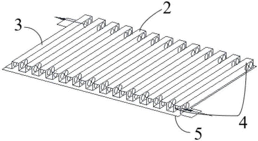
[0056] Please refer to Figure 1 to Figure 7 In this embodiment, the hot wall heat exchanger includes a hot wall 1, the hot wall 1 includes an internal support device 2 and a heat exchange partition 5 that wraps the internal support device 2, and the interior of the hot wall 1 is evacuated and injected into a phase change For fluid, the internal support device 2 includes a middle section 3 for the phase change fluid to circulate up and down and upper and lower ends 4 for the phase change fluid to circulate left and right; the hot wall 1 is rectangular, and several hot walls 1 of the same size are arranged side by side in clusters, or , The hot wall 1 is annular, and several hot walls 1 of different sizes are nested layer by layer in clusters; each adjacent hot wall 1 is provided with channel strips 6 or fins that support pressure and facilitate the passage of fluids 16; Divide all the fluid side of the channel strips 6 or fins 16 outside the hot wall 1 into multiple areas, including the heat absorption area and the heat release area, and contact with the hot wall 1 through the phase change fluid in the hot wall 1 The long-distance heat exchange of the heat exchange fluid.
[0057] The basic principle of the hot wall heat exchanger and the heat pipe heat exchanger proposed in the present invention are the same, but the structure is very different. One is a tube type and the other is a plate type. The advantage is that the compactness is higher than that of the current heat pipe, which is convenient The design optimization can adapt to more heat exchange fields. There is no mutual resistance between the gas phase and the liquid phase. The gas phase and the liquid phase have their own special channels. There is no resistance of the liquid phase caused by capillary tension, which makes the phase change fluid circulation speed. Speed up and improve heat exchange efficiency.
[0058] Specifically, the transverse channel formed by the through hole or opening at the upper end of the support device 2 in the hot wall 1 takes the gaseous phase (after evaporation) fluid, and the same transverse channel opened at the lower end takes the liquid phase fluid. If the internal support device 2 is absorbing heat The zone is the channel through which the phase change fluid evaporates, and if it is in the exothermic zone, it is the channel through which the liquid phase of the phase change fluid falls. It can be seen that the function of the internal support device 2 built into the hot wall 1 is to realize the separation of the two fluids of the gas phase and the liquid phase. In addition, it also mainly supports the extrusion of the outer fluid (that is, the fluid that needs heat exchange) against the hot wall 1 to prevent heat Wall 1 is recessed.
[0059] It can be seen that since the hot wall 1 adopts a thinned heat exchange partition 5 to reduce costs and improve heat exchange efficiency, the supporting force between the hot walls 1 needs to be strengthened. Various forms of channel support strips and force-bearing rectangular fins 16 can be used. , On the one hand, it can improve the strength to withstand fluid pressure, on the other hand, it can expand the heat exchange area in a limited volume, such as Figure 7 The channel strip 6 shown can be placed between the annular hot walls 1, and the channel strip 6 can also be placed between the rectangular hot walls 1, and there is a channel support strip as shown in FIG. 6, which has fins in the channel 16. It can be stuffed into the hot wall one by one, or taken out one by one for cleaning. The inner support device 2 in the hot wall 1 is shown in Figures 2 and 4, which is similar to the rectangular fin 16, except that the upper and lower fins 16 have through holes to facilitate the horizontal flow of the phase change fluid in the hot wall 1. When the hot wall 1 is used as a heat-absorbing element, the phase-change fluid evaporates and flows upward along the groove formed in the middle section 3 shown in Fig. 2 or Fig. 4, and the gas-phase fluid of each groove converges into the communicating channel device on the upper corner side. The gas-phase fluid in the communicating channel device of the heat release area is then divided to release latent heat in the grooves of the condensing hot wall 1, and the liquid phase fluid after releasing the latent heat is converged into the communicating channel on the lower corner side and flows to the heat absorption area through this; The rectangular fins 16 shown in Fig. 2(a) and Fig. 4(a) not only play a certain supporting role, but also provide a channel for the phase change fluid to flow up and down. The upper and lower edges of the fin 16 are not completely enclosed and can provide The space in which the phase-change fluid flows horizontally; while in Figure 2(b) and Figure 4(b), it is the entire rectangular fin 16 covering the rectangular hot wall 1, except that the upper and lower ends 4 of the fin 16 are notched. Facilitate the horizontal flow of phase change fluid.
[0060] 1 and 3, when a single rectangular hot wall 1 or an annular hot wall 1 relatively independently completes the circulation of the internal phase change fluid, there is no need to provide inlets and outlets, and there is no need to provide a connecting pipe 7. The rectangular hot wall 1 and the annular hot wall 1 that are not connected to each other have an evaporation section and a condensation section, which are similar to the current heat pipe. The axial heat pipe must be divided into a heat absorption section and a heat release section, while the radial heat pipe releases heat in the center of the heat pipe and absorbs heat outside the tube core. In the present invention, a single hot wall 1 can be divided into a heat absorption part and a heat release part, or A single hot wall 1 is completely used as a heat-absorbing hot wall 1 and a heat-releasing hot wall 1, while the annular hot wall 1 is used as a heat-absorbing (or heat-releasing) hot wall 1 to realize ultra-long distance heat exchange.
[0061] Referring to Figure 5(a), each rectangular hot wall 1 or annular hot wall 1 communicates with each other through a pipe 7 to complete the circulation of the internal phase change fluid, and transfer heat through phase change in an overall coordinated manner. Please refer to Figure 5(b). A pair of pipes 7 are required to form the hot wall 1 cluster, and they are arranged diagonally up and down. The upper pipe 7 is for gas phase fluid (after evaporation), and the lower pipe 7 is for liquid phase (after condensation). For fluid, the pipe 7 is a half pipe, and the half pipe is provided with a through hole communicating with the phase change fluid inlet and outlet. According to the actual heat exchanger structure, the cross section of the half pipe is semicircle (please refer to Figure 8(a)) or rectangular (please refer to Figure 8(b)) or one end is round and the remaining part is semicircle (please refer to Figure 8( c)).
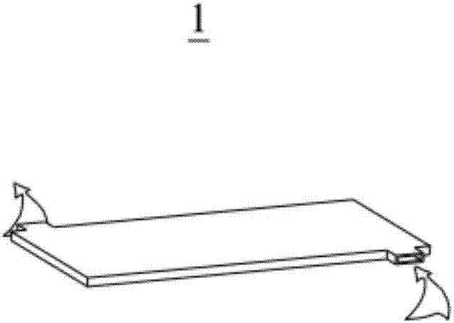
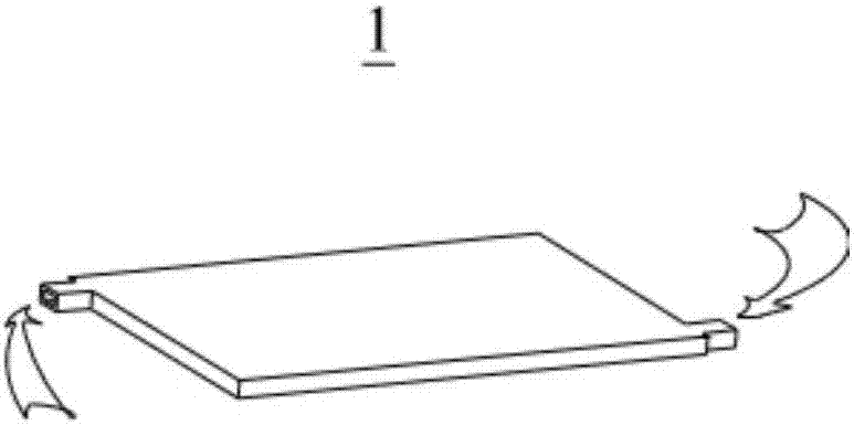
[0062] The hot wall heat exchanger provided by the present invention can realize multi-directional flow of heat exchange fluid. Please refer to Figure 1(a), the rectangular hot wall 1 is placed vertically, and the inlet and outlet direction of the phase change fluid is parallel to the setting direction of the inner support device 2, so that the heat exchange fluid flows in the horizontal direction. This method is suitable for the end of the air conditioner the design of. 1(b), the rectangular hot wall 1 is placed vertically, and the inlet and outlet direction of the phase change fluid is perpendicular to the setting direction of the inner support device 2, so that the heat exchange fluid flows in the vertical direction. The vertical method not only saves space and reduces land occupation, but also facilitates maintenance and installation.
[0063] Preferably, the pipeline 7 is connected to an external device for disposing of the phase change fluid, and the external device includes at least one of a defrosting device, a compressor or a circulating pump for heating the phase change fluid. The power provided by external devices such as compressors or circulating pumps for the phase change fluid can achieve ultra-long-distance heat exchange.
[0064] Preferably, several annular hot walls 1 with similar shapes are enclosed in an elliptical ring, a rounded rectangular ring (please refer to Figure 3(a)) or a preset shape, and the center of the hot wall heat exchanger is provided with a shaped ring, which is shaped On the periphery of the ring, there are a circle of annular hot walls 1 similar in shape to the ring. All the hot walls 1 and their associated channel strips 6 or fins 16 are tightly bound by an outer thick-walled ring 8 that can bear pressure. Since the channel strips 6 or fins 16 supporting each other between the annular hot walls 1 can finally transmit its internal pressure to the outermost thick-walled ring 8, the annular hot-wall heat exchanger has a relatively high performance under the action of the outermost thick-walled ring 8. The pressure resistance is large, and the wall thickness of the outermost thick-walled ring 8 can be large without affecting the heat exchange efficiency.
[0065] Please refer to Figure 3(b), the annular hot wall 1 is also provided with an expansion fold 9. Due to the thermal expansion of the internal fluid, in order to prevent damage to the hot wall 1 due to expansion, a stretchable fold is provided, which can finally transmit the expansion force to the outermost thick-walled ring 8.
[0066] Please refer to Picture 9 , The hot wall heat exchanger also includes a housing 10 that contains the annular hot wall 1, an upper cover 11 detachably connected to the housing 10, and a lower cover 12 that is not detachably connected to the housing 10, and the housing 10 is connected to the lower cover 12 A volume cavity 13 is formed through, the lower cover 12 is provided with a cleaning fluid side inlet and outlet channel, and one of the channels passes through the lower cover 12 to communicate with the central cavity of the heat exchanger. The hot-wall heat exchanger proposed in this embodiment can be cleaned on both sides during operation. This is because the hot-wall heat exchanger can be designed such that the upper cover 11 is not connected to the circulation pipe that exchanges heat with the phase change fluid. When the flow of fluid in and out of the cleaning side is adjusted properly, there will be no fluid overflow, and the sewage can be discharged from the lower position of the lower non-detachable head during cleaning. The previous multi-layer coaxial cylindrical fin 16 heat exchanger is inconvenient to clean the dirt on the heat exchange partition 5. When the gun is opened, one end of the fin 16 cannot be passed through, especially when it is difficult to manufacture, there will always be fin 16 It is difficult to connect tightly with the partition wall, causing the thin wall to burst after being pressed: The annular hot-wall heat exchanger can achieve the high efficiency of the plate heat exchanger, and at the same time, the pressure resistance characteristics of the shell-and-tube heat exchanger can be realized because of its The inner ring-shaped thin wall nested in layers is provided with an expansion fold 9, so that the internal fluid pressure can be transmitted to the outermost thick-walled ring 8 through the expansion fold 9. This thick-walled ring 8 can tightly clamp the inner hot walls 1 and the associated channel strips 6 or fins 16. Like a rectangular hot-wall heat exchanger, the outer layer adopts a pressure-resistant clamping plate of appropriate thickness. Forced support channel strip 6. Small size, less space, comparable to plate heat exchangers, and more convenient to clean than plate heat exchangers and shell-and-tube heat exchangers. At the same time, it creates a way to clean the heat exchange walls while running, which cannot be achieved by all current heat exchangers. 5 technology precedents, and unprecedented realization of numerous heat exchange applications, its coverage exceeds any major type of heat exchanger equipment types, and similar heat pipe heat exchange methods are applied to more and more extensive fields.
[0067] Based on Picture 9 To illustrate the annular hot-wall heat exchanger, the annular hot-wall heat exchanger includes an annular hot wall 1, a channel strip 6 and a thick-walled ring 8. Picture 9 The annular hot wall 1 in Figure 3(b) can be the annular hot wall 1 as shown in Figure 3(b). The channel strips 6 or fins 16 are as shown in Figure 4, and the phase change fluid distribution channel 14 and the phase change fluid confluence channel 15 are arranged in The diagonal positions of the heat exchanger are all half-pipe communication channels as shown in Figure 8(c). The channel strip 6 at the lower part of the communication channel must be closed to prevent the leakage of phase change fluid and heat absorption (or Heat release) fluid flows into the center tube of the heat exchanger from the heat absorption (or heat release) fluid outlet channel, flows into the volume cavity 13 after heat exchange through the hot wall 1, and finally flows out from the heat absorption (or heat release) fluid outlet channel at the lower end , The hot wall heat exchanger can realize ultra-long-distance heat exchange, and the phase change fluid in the annular hot wall 1 can be transported to a far place by a compressor or a circulating pump to release heat (or absorb heat). ) Fluid conducts heat exchange, which is more meaningful than the current heat pipe for long-distance heat exchange. In fact, the endothermic fluid and the exothermic fluid can be far apart, and the heat exchange between them is through the phase change fluid in the annular hot wall 1. It is very suitable for the evaporator and condenser of the central air conditioner and the condenser of the thermal power plant to realize the efficient heat exchange like the plate heat exchanger, and the scale cleaning is better than the shell-and-tube heat exchanger. It is also convenient, because when the upper cover 11 is opened for cleaning, there is no need to completely close the inlet and outlet valves of the heat exchange fluid, just adjust the opening and closing degree of the inlet valve to prevent the fluid from overflowing (discharge through the lower drain valve, and Add water in time), the cleaning process can not affect the operation of the unit, nor will it cause pollution to the surrounding environment of the unit.
[0068] Several rectangular hot wall heat exchangers are provided below.
[0069] Please refer to Picture 10 , It is the first embodiment of the hot wall heat exchanger that realizes the heat exchange between liquid and air. There is a small section at one end of the heat exchanger divided into liquid heat absorption (or heat release) volume area A, which is wrapped by a cavity shell to correspond to a larger heat release (endothermic) area with a smaller heat absorption (heat release) area B area (because the air heat transfer coefficient is small, a larger heat exchange area is required) to adapt to a wider range of applications. It can be used as a cooling and heat dissipation device, surface cooler, such as central air conditioning terminal, automobile water tank, etc., specifically, The gaseous fluid enters and exits from the right end of the B zone. The fin 16 between the adjacent hot walls 1 is an air heat exchange fluid fin 16. The side of the fin 16 is also provided with a seal, which forms the air side fin and The seals on both sides are a series of phase-change heat devices which are arranged alternately with rectangular heat walls to form a whole. A small part of the device is placed in area A and is wrapped by the volume cavity 17 of this area. It can be understood that area A A volumetric cavity 17 for accommodating the fluid that exchanges heat with the gaseous fluid is arranged inside, and a detachable cover 18 is also provided on the volumetric cavity 17. There are rectangular hot walls and fins inside 17 for the hot wall heat exchanger. The fluid side pressure drop that exchanges heat with the gaseous fluid is very small, which can greatly save the power of the circulating pump, and there is no risk of clogging, and it is also convenient to clean. It can be used as a condenser in thermal power plants and nuclear power plants, which can greatly increase power generation efficiency. Improved, the failure rate is greatly reduced, and the reliability of operation is enhanced. It can also be used as a heat source tower to absorb cheap heat energy in the air. It can eradicate the world’s old problems of defrosting because it can connect the hot wall 1 through the heating device. It can make the phase change fluid gain heat and increase the enthalpy, and it is convenient to remove the frost on the outer fin 16 of the hot wall 1, and even the heat energy of defrosting is not wasted, and unlike all current defrosting technologies, it will affect heating. It is necessary to obtain heat from indoors for defrosting, or delay the time of heat production. Whether it is reverse operation defrosting or direct heating defrosting method, it will cost a lot of energy consumption. It seems that the gain is not worth the loss. It is not as cost-effective to use boiler heating in winter. Since the fins 16 are perpendicular to the ground, and heat can be quickly transferred from the fins 16 or the partition wall to the roots of the frost, the frost can fall before all of it is melted, and the latent heat of water vapor in the air is also used. This is a kind of Very cost-effective defrosting technique. Configure the heating volume cavity and connect it to the connecting device of the hot wall 1, so that the phase change fluid can transfer heat to the fin 16 between the hot wall 1 and the hot wall 1, and dissipate the heat to the room for heating. The phase change fluid It is recondensed into liquid and flows back into the heating volume cavity again, and its structure is more compact and beautiful, suitable for indoor heat sink devices.
[0070] Please refer to Picture 11 , The second embodiment of the hot wall heat exchanger that can exchange heat between liquid and air. Refrigerant water (or warm water) enters the heat release (or heat absorption) area from the refrigerant water inlet 19 (or warm water inlet) into the enclosed volume cavity 17 of the heat release (or heat absorption) area, and exchanges heat with the rectangular hot wall 1 from the refrigerant water outlet 20 (Or warm water outlet), the condensed water flows out from the condensate outlet 21 at the lower end, the hot wall heat exchanger is also provided with a centrifugal fan 22, the centrifugal fan 22 is matched with the air outlet channel 23 provided on the heat exchanger To speed up air circulation, the heat exchanger replaces the existing fan coil as the end of the central air conditioner, which can greatly reduce the energy consumption of the main engine.
[0071] Please refer to Picture 12 , In order to realize an embodiment of the hot wall heat exchanger for heat exchange between liquid and liquid, C fluid and D fluid carry out long-distance heat exchange and can be cleaned on both sides, which can replace the current plate heat exchanger and shell-and-tube type Heat Exchanger. It can also be designed as a three-fluid heat exchange based on this method, one is the endothermic zone, or two are the exothermic zone.
[0072] Please refer to Figure 13 , In order to realize an embodiment of a hot wall heat exchanger for heat exchange between air and air, it includes a rectangular hot wall 1 cluster, heat exchange fins 16 arranged between adjacent hot walls 1, and communicating hot walls 1 for pipeline 7. The indoor air enters from the area below the heat exchanger. After passing through the hot wall 1 to exchange heat, it is discharged from the upper area. The upper and lower areas are separated by cold and hot partition plates. This heat exchanger is particularly suitable for use as a fresh air blower.
[0073] It can be seen from the above that, in addition to the advantages of heat pipe heat exchangers, hot wall heat exchangers also have at least the following advantages: (1) The heat exchange area per unit volume is much larger than that of heat pipe heat exchangers, making them more compact, because The heat pipe with the same surface area occupies more space than the hot wall1; (2) The application field is more extensive, which can adapt to the heat exchange of various flow forms of the heat exchange fluid in multiple directions, vertical, horizontal and oblique, unlike the heat pipe heat exchanger. Make the choice of radial or axial heat pipe and not place it at an oblique angle; (3) Whether it is the heat exchange between liquid and liquid, or gas and gas, or liquid and gas, or liquid and air, or gas and air, Hot wall heat exchangers will show efficient and economical use, but the current various heat pipe heat exchangers cannot economically completely replace plate heat exchangers, shell-and-tube heat exchangers, plate-fin heat exchangers and tube-type heat exchangers. Finned heat exchangers are used in many fields; (4) The internal phase change fluid is more smoothly divided, because the internal two-phase flow is difficult to mix and there is no interphase resistance. They go through the condensation channel and the evaporation channel respectively, which can accelerate the evaporation The circulation speed of the condensed phase change fluid; (5) The fluid resistance outside the hot wall 1 is smaller than that of the heat pipe, and its pressure drop is also smaller than that of the heat pipe; (6) The pressure resistance of the annular hot wall heat exchanger under the action of the outermost thick-walled ring 8 Larger than the existing heat pipe heat exchanger, because there are mutually supporting channel strips 6 or fins 16 between the annular hot wall 1, the internal pressure can be finally transferred to the outermost thick-walled ring 8, and the annular hot wall 1 can also be provided with expansion folds 9. The internal pressure is transferred to the thick-walled ring 8 through expansion, and the wall thickness of the outermost thick-walled ring 8 can be larger without affecting the heat exchange efficiency; (7) The hot wall 1 combination is more flexible and diverse than the heat pipe combination. The hot-wall heat exchanger that is more suitable for the application scenario can be designed according to the actual situation. Its application diversity is much more than that of heat pipes. In particular, the heat exchanger formed by the rectangular hot wall 1 has more advantages, because it does not necessarily require a single One part of the hot wall 1 is placed in the heat absorption zone as the evaporation section, and the other part is placed in the heat release zone as the condensation section. Instead, a single hot wall 1 can be placed in the heat absorption zone or the condensation zone as a whole, and the heat absorption zone and The heat release area can be divided into multiple areas, which is not possible with the current heat pipe heat exchanger. The heat pipe heat exchanger must be that one section of each heat pipe is placed in the heat release area, and the other section is placed in the heat absorption area (its internal The evaporation section and the condensation section are formed, and the two regions formed by the two sections are difficult to isolate each other, and leakage is prone to occur. If the outer wall of the heat pipe has fins, use metal materials to divide it into heat absorption and heat release areas. The area is quite difficult, and it will cost a lot of processing costs, especially when the pressure difference between the two areas is relatively large, it is even more embarrassing; (8) The cost is lower than that of the heat pipe. According to the actual application scenario, the heat exchange partition can be 5 Thinning, the current heat pipe heat exchanger is difficult to compare with, because the pressure of the hot wall 1 is carried by the outer thick-walled ring 8 or the thick-walled force-bearing splints at both ends, unlike heat pipes that require each heat pipe material The thickness is used as the pressure bearing, so the metal material consumption of the hot wall 1 is much less, and the pressure resistance will be improved; (9) The equipment maintenance is more convenient than the current heat pipe, the leakage point is easy to find, the welding is convenient for leaking, and the extraction is not condensed. Sexual gas is also easy , The phase change fluid injection can be completed at one time, and the design scheme of cleaning while running can also be realized; (10) The heat pipe can exchange heat remotely, and the hot wall 1 can not only exchange heat remotely, but also can use the compressor Or circulating pumps to achieve ultra-long-distance heat exchange; (11) It is difficult for heat pipes to realize that the evaporation area (heat source) is multiple areas or the condensation area (cold source) is multiple areas, while the rectangular connected hot wall heat exchanger is easy Realize multiple evaporation zones or multiple condensation zones; (12) The fouling coefficient will be much lower than that of the heat pipe, and the fouling is not as obvious as the heat pipe, because the hot wall 1 and the fin 16 are perpendicular to the ground.
[0074] The above descriptions are only the preferred embodiments of the present invention, and do not limit the scope of the present invention. Under the concept of the present invention, equivalent structural transformations made by using the contents of the description and drawings of the present invention, or directly/indirectly applied to Other related technical fields are included in the scope of patent protection of the present invention.
Login to view more PUM


Description & Claims & Application Information
We can also present the details of the Description, Claims and Application information to help users get a comprehensive understanding of the technical details of the patent, such as background art, summary of invention, brief description of drawings, description of embodiments, and other original content. On the other hand, users can also determine the specific scope of protection of the technology through the list of claims; as well as understand the changes in the life cycle of the technology with the presentation of the patent timeline. Login to view more.
Login to view more Similar technology patents
Self-restoration concrete with enhanced restoration property and preparation method thereof
Owner:SOUTH CHINA UNIV OF TECH
Integrated electric driving system assembly and electric vehicle
ActiveCN109353201AImprove compactnessImprove reliabilityElectric propulsion mountingPropulsion coolingBreakout boxElectric drive
Owner:重庆长安新能源汽车科技有限公司
Green rapid-hardening early-strength magnesium phosphate-based healant and preparation method thereof
ActiveCN104909709AImprove compactnessHigh impermeability levelSolid waste managementSilica fumeMagnesium orthophosphate
Owner:WUHAN MUNICIPAL CONSTR GROUP +1
Fiber packing preparation method
ActiveCN102678922AFully impregnatedImprove compactnessEngine sealsVegetal fibresLubricationParaffin oils
Owner:慈溪博格曼密封材料有限公司
Classification and recommendation of technical efficacy words
- Improve compactness
Ultra-compact and highly portable absorbent articles
Owner:DIAPEROOS
Automatic edible fungi bag filler
InactiveCN102396344AImprove uniformityImprove compactnessPackagingHorticultureEngineeringFill device
Owner:徐寿海 +1
Sintered composite soft magnetic material and method for preparing same
ActiveCN102651264ALower sintering temperatureImprove compactnessInorganic material magnetismRare-earth elementMagnet
Owner:GRIREM ADVANCED MATERIALS CO LTD