
Common port coupling device and microwave cavity device

A technology of coupling device and common port, which is applied to waveguide-type devices, connecting devices, resonators, etc., can solve the problems of complex structure, difficult processing, and inability to meet the application requirements of high and low frequency channels, and achieves simple structure and suitable for batches. production effect

Pending Publication Date: 2017-11-24
COMBA TELECOM TECH (GUANGZHOU) CO LTD
View PDF7 Cites 0 Cited by
  • Summary
  • Abstract
  • Description
  • Claims
  • Application Information

AI Technical Summary

Problems solved by technology

Among them, the microwave cavity combiner is composed of multiple filter channels. When the cavity combiner includes high-frequency and low-frequency channels, the design of its common port is particularly complicated.
[0003] In the prior art, there is a port coupling structure design with very wide port bandwidth, such as the cavity device and its resonant channel connection port coupling structure disclosed in CN102306860A , the design is a rod-insert coupling structure that can achieve a wide coupling bandwidth, but its limitation is that it can only be applied to the case of an average high-frequency path or a low-frequency path, and cannot meet the application requirements that include both high-frequency and low-frequency paths
[0004] The utility model patent with the publication number CN203326071U discloses an ultra-wideband dual-frequency combiner, which passes through a ladder network with series branches and parallel branches The dual-band filter circuit composed of the above-mentioned form realizes a wide bandwidth design and can include high-frequency and low-frequency channels at the same time. The influence of non-linear factors is large

Method used


Image

  • Common port coupling device and microwave cavity device
  • Common port coupling device and microwave cavity device
  • Common port coupling device and microwave cavity device

Examples


Embodiment Construction

[0030] Embodiments of the present invention are described in detail below, examples of which are shown in the drawings, wherein the same or similar reference numerals designate the same or similar elements or elements having the same or similar functions throughout. The embodiments described below by referring to the figures are exemplary only for explaining the present invention and should not be construed as limiting the present invention.

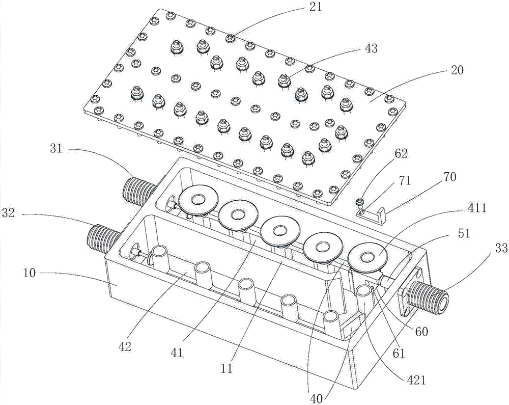
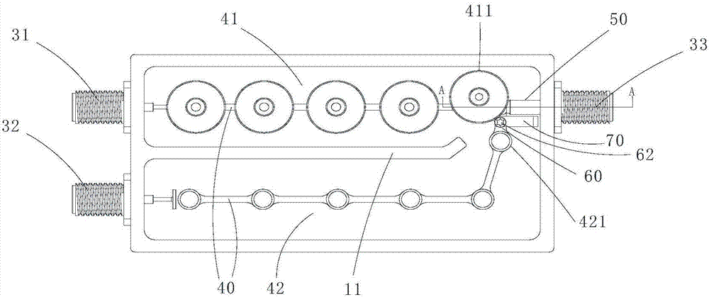
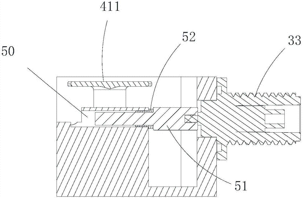
[0031] see Figure 1 to Figure 3 , the embodiment of the present invention provides a common port coupling device. The common port coupling device includes: a cavity body 10, a cover plate 20 connected to the upper part of the cavity body 10 for forming a closed space for signal transmission with the cavity body 10, and two ports arranged at one end of the cavity body 10 for connecting to the inside of the cavity body 10 respectively. Signal ports 31 , 32 of the two resonant paths 41 , 42 and a common port 33 provided at the other end o...


PUM


Abstract

The invention provides a common port coupling device, which comprises a cavity, a cover plate, signal ports and a common port, wherein the signal ports are arranged on one end of the cavity and used for being connected with resonant circuits in the cavity, and the common port is arranged at the other end of the cavity; the resonant circuits comprise a high-frequency circuit and a low-frequency circuit, each resonant circuit is at least composed of one resonant column, the high-frequency resonant column close to the common port is the first high-frequency resonant column, and the low-frequency resonant column close to the common port is the first low-frequency resonant column; a coupling hole is formed in one side, facing the common port, of the first low-frequency resonant column, and a coupling rod which is connected with the first low-frequency resonant column in a capacitive coupling manner is inserted in the coupling hole; and the first high-frequency resonant column is connected with a coupling piece, and the coupling piece is parallel to and coupled with the coupling rod. The common port coupling device is applicable to arbitrary one of microwave cavity devices such as a combiner, a duplexer, a filter and a feed, can meet the bandwidth requirements of the high and low frequency resonant circuits with broad bandwidths, is simple in structure and requires no welding, significantly reduces the impact of nonlinear factors on the stability of the ports, and is suitable for mass production.

Description

technical field [0001] The invention relates to the field of mobile communication devices, in particular, the invention relates to a common port coupling device and a microwave cavity device adopting the structure of the device. Background technique [0002] With the development of modern mobile communication, microwave devices composed of microwave filters have become an indispensable part of mobile communication technology, and in order to meet the application requirements, the market has higher and higher requirements for microwave devices. While the port bandwidth is sufficiently wide, strict intermodulation index requirements must also be met. Among them, the microwave cavity combiner is composed of multiple filter channels. When the cavity combiner includes high-frequency and low-frequency channels, the design of its common port is particularly complicated. [0003] In the prior art, there is a port coupling structure design with a very wide port bandwidth, such as th...

Claims


Application Information

Patent Timeline
IPC IPC(8): H01P5/12H01P7/06
CPCH01P5/12H01P7/06
Inventor 谢振雄孟弼慧周国明陈振浩靳雲玺
Owner COMBA TELECOM TECH (GUANGZHOU) CO LTD
Learn More