LED driving circuit

A technology of LED driving and switching driving circuits, which is applied in the field of circuits to achieve the effects of improving PFC, improving compatibility, and improving dimming characteristics

Active Publication Date: 2017-11-24
上海奥简微电子科技有限公司
View PDF8 Cites 2 Cited by
  • Summary
  • Abstract
  • Description
  • Claims
  • Application Information

AI Technical Summary

Problems solved by technology

But at present, in the field of lighting, LED still has some unsatisfactory disadvantages in technology. The traditional LED drive circuit can only

Method used


Image

  • LED driving circuit

Examples


Embodiment Construction

[0010] The preferred embodiments of the present invention are given below in conjunction with the accompanying drawings to describe the technical solution of the present invention in detail.

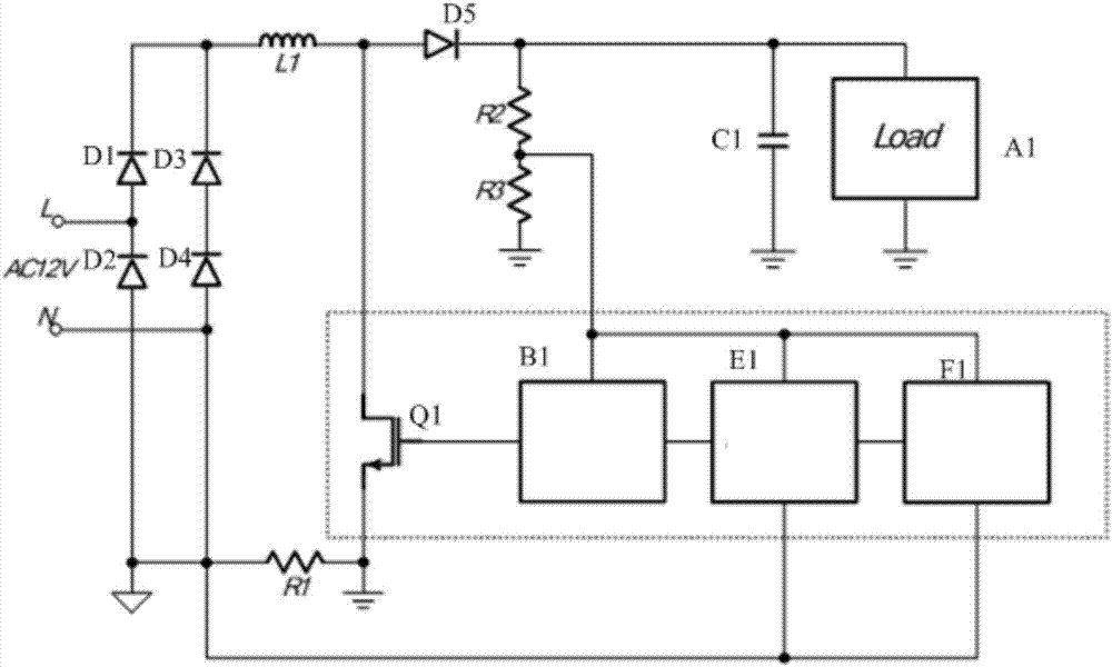
[0011] Such as figure 1 As shown, the LED driving circuit of the present invention includes a load A1, a switch driving circuit B1, an electronic transformer compatible circuit E1, a power factor correction circuit F1, a 12V AC power supply, a first inductor L1, a first capacitor C1, a first triode Q1, The first resistor R1, the second resistor R2, the third resistor R3, the first diode D1, the second diode D2, the third diode D3, the fourth diode D4, the fifth diode D5, The load A1 is connected in parallel with the first capacitor C1, the first inductor L1, the fifth diode D5, the second resistor R2 and the third resistor R3 are connected in series, the first diode D1 is connected with the third diode D3, and the fourth diode The tube D4 is connected in parallel, the first diode D1 is ...


PUM


Abstract

The invention discloses an LED driving circuit which comprises a load which is connected to a first capacitor. A first inductor, a fifth diode, a second resistor and a third resistor are connected in series. A first diode is connected to a third diode and a fourth diode in parallel. The first diode is connected to a 12V AC power supply in parallel. A second diode is connected to the 12V AC power supply in parallel. A switch driving circuit is connected to an electronic transformer compatible circuit in parallel. The electronic transformer compatible circuit is connected to a power factor correction circuit in parallel. A first resistor is connected to the electronic transformer compatible circuit in parallel. The switch driving circuit is connected to a third resistor in parallel. The LED driving circuit has the advantages of a small size and stability in use, the PFC is greatly improved, the compatibility of an ET is improved, the dimming characteristic is improved, the system application is integrated and peripheral devices are reduced, and the cost is reduced at the same time.

Description

technical field [0001] The invention relates to a circuit, in particular to an LED (light emitting diode) drive circuit. Background technique [0002] With the development of today's electronic technology and electronic industry, LED lighting equipment has been widely used in people's life and production. At the same time, LED lighting equipment has excellent market prospects because of its low energy consumption, environmental protection, and convenient control. But at present, in the field of lighting, LED still has some unsatisfactory disadvantages in technology. The traditional LED drive circuit can only take into account the compatibility with ET (electronic transformer), and cannot be used for PFC (Power Factor Correction, power factor correction). Contents of the invention [0003] The technical problem to be solved by the present invention is to provide a LED drive circuit, which is small in size and stable in use, greatly improves PFC (Power Factor Correction, po...

Claims


Application Information

Patent Timeline
IPC IPC(8): H05B33/08H05B44/00
CPCH05B45/37H05B45/00
Inventor 陈培元
Owner 上海奥简微电子科技有限公司
Why Eureka
Try Eureka