Bidirectional spiral flow channel water cooling device

A two-way spiral, water-cooled heat dissipation technology, applied in cooling/ventilation/heating transformation, modification by conduction heat transfer, etc. Reasonable and other issues, to achieve the effect of easy installation, disassembly and maintenance, suitable for lightweight, fast and uniform heat dissipation

Inactive Publication Date: 2017-11-24
CRRC YONGJI ELECTRIC CO LTD
View PDF12 Cites 6 Cited by
  • Summary
  • Abstract
  • Description
  • Claims
  • Application Information

AI Technical Summary

Problems solved by technology

[0005] The invention solves the problems that the existing water-cooling and heat-dissipating device occupies a large area, the flow channel design and layout are unreasonable, the installation and disassembly maintenance is inconvenient, the machining accuracy is high, and the water joint interferes with the peripheral metal support frame, and provides a two-way spiral flow channel for water cooling and heat dissipation device
The two-way spiral flow channel maximizes the use of the space on the heat sink plate surface, and there are no sharp or right angles. The flow channel is smooth. The flow rate of the coolant is from the outer ring to the inner ring, and then from the inner ring to the outer ring. The resistance encountered is uniform and does not change much. , which perfectly solves the problems of uneven overall heat dissipation of the heat sink, the surface temperature of the heat sink changes with the flow direction of the coolant, the large flow resistance is not easy to dissipate heat, and the layout of power devices is limited by the flow channel, etc.

Method used


Image

  • Bidirectional spiral flow channel water cooling device
  • Bidirectional spiral flow channel water cooling device

Examples


Embodiment Construction

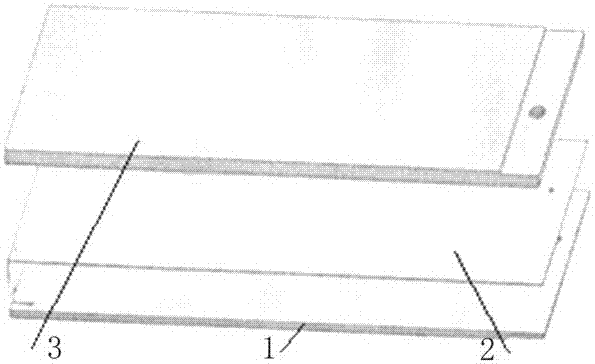
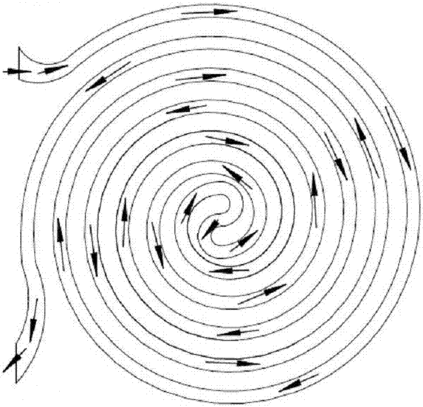
[0011] The two-way spiral flow channel water-cooling heat dissipation device is composed of three layers of cooling main board 1, brazing plate 2, and cover plate 3; the cooling main board 1 is provided with a bidirectional spiral flow channel that is centrally symmetrical and smoothly connected through the center of symmetry. The cover plate 3 is provided with two water joints perpendicular to the cover plate surface, and the water joints are respectively connected with the two ends of the flow channel; the cover plate 3 and the cooling main board 1 are provided with a plurality of mounting threaded holes.

[0012] During specific implementation, the water connector is arranged on the side edge of the water-cooled main board 1 and arranged parallel to the water-cooled main board 1 .

[0013] During specific installation and use, according to the installation requirements of the external interface, the docking position of the water connector and the flow channel should be reaso...


PUM


Abstract

The invention relates to a large power device water cooling device and especially relates to a bidirectional spiral flow channel water cooling device. An existing water cooling device occupies a large area, a design and layout of a flow channel is unreasonable, power device layout is limited, installation and dismounting maintenance is inconvenient, a processing precision requirement is high, and a water joint and a peripheral metal support framework are intervened. By using the device of the invention, the above problems are solved. The device is characterized in that a cooling main board, a soldering plate and a cover plate are included; the cooling main board is provided with a bidirectional spiral flow channel which is in a central symmetry state, wherein a symmetric center smoothly passes through the bidirectional spiral flow channel; the cover plate is provided with two water joints which are vertical to a cover plate surface, and the water joints are connected to two ends of the flow channel; and the cover plate and a board surface of the cooling main board are provided with a plurality of installation screwed holes. The device has the following advantages that a non-uniform cooling problem is solved; the water joints can be conveniently installed, dismounted and maintained, are not intervened, and processing precision is low; a cooling liquid flows smoothly so that cooling is fast and uniform, and power device layout is simple; and there is no metal framework, an occupation area is small, and the device possesses light weight and is in a small size.

Description

technical field [0001] The invention relates to a water-cooling and heat-radiating device for high-power devices, in particular to a water-cooling and heat-radiating device with bidirectional spiral channels. Background technique [0002] Power devices such as IGBTs, power diodes, power resistors, and SiC-IGBTs are widely used in wind power, solar energy, rail transit, automobiles and other industries. Especially in the rail transit industry, due to the rapid development of high-power AC drive technology, high-power power devices are increasingly widely used, and their heat dissipation problems are becoming increasingly prominent. The water-cooled heat dissipation device can solve the heat dissipation problem of power devices with power consumption of 10kW and above, and has been widely used in the rail transit industry. The existing water-cooling and heat dissipation device is a substrate with a water flow channel inside, and water joints parallel to the surface of the sub...

Claims


Application Information

Patent Timeline
IPC IPC(8): H05K7/20
CPCH05K7/20H05K7/20509
Inventor 李守蓉杨春宇王雷赵一洁郑旭阳
Owner CRRC YONGJI ELECTRIC CO LTD
Why Eureka
Try Eureka