Coupling welding machine

A welding machine and laser welding technology, applied in welding equipment, laser welding equipment, metal processing equipment, etc., can solve the problem that the height of the welding torch head cannot be accurately controlled, and achieve the effect of maintaining consistent height and ensuring positional accuracy

Pending Publication Date: 2017-11-28
深圳市大族锐波传感科技有限公司
View PDF13 Cites 2 Cited by
  • Summary
  • Abstract
  • Description
  • Claims
  • Application Information

AI Technical Summary

Problems solved by technology

[0005] The embodiment of the present invention provides a coupling welding machine, which aims to solve

Method used


Image

  • Coupling welding machine
  • Coupling welding machine
  • Coupling welding machine

Examples


Example Embodiment

[0030] In order to make the object, technical solution and advantages of the present invention clearer, the present invention will be further described in detail below in conjunction with the accompanying drawings and embodiments. It should be understood that the specific embodiments described here are only used to explain the present invention, not to limit the present invention.

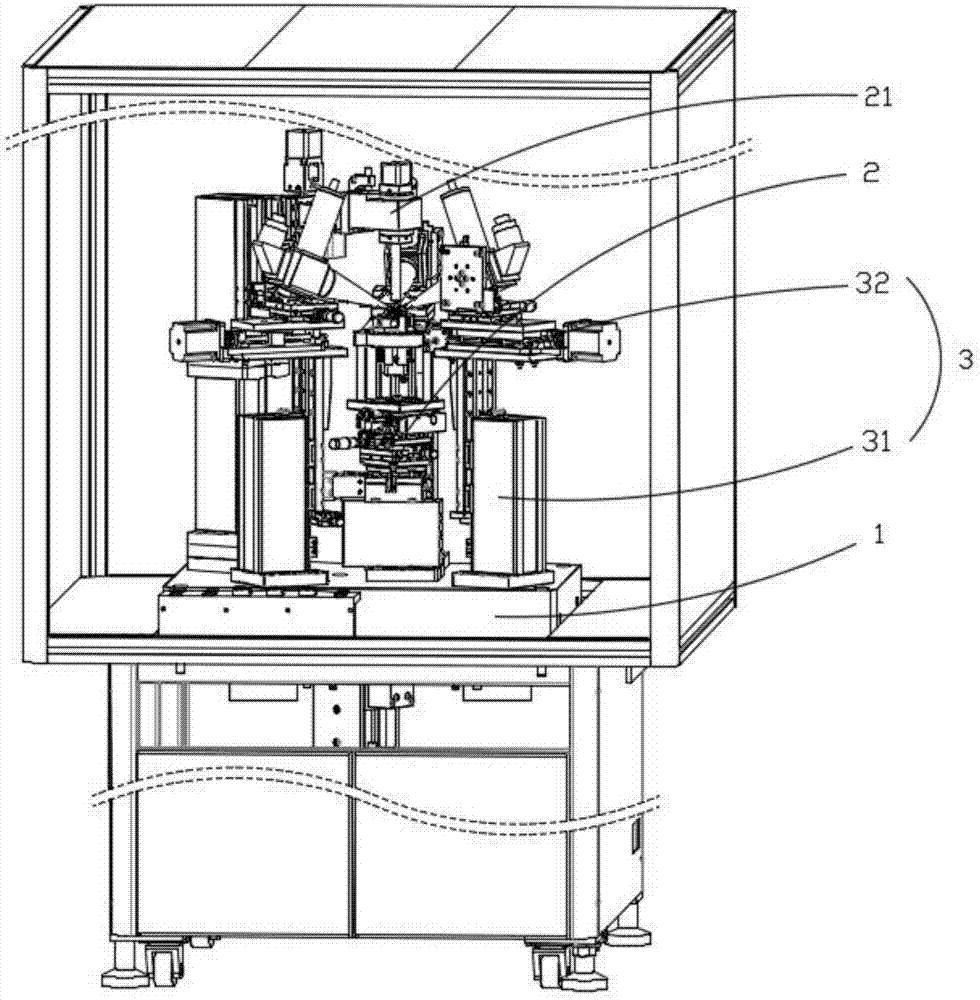
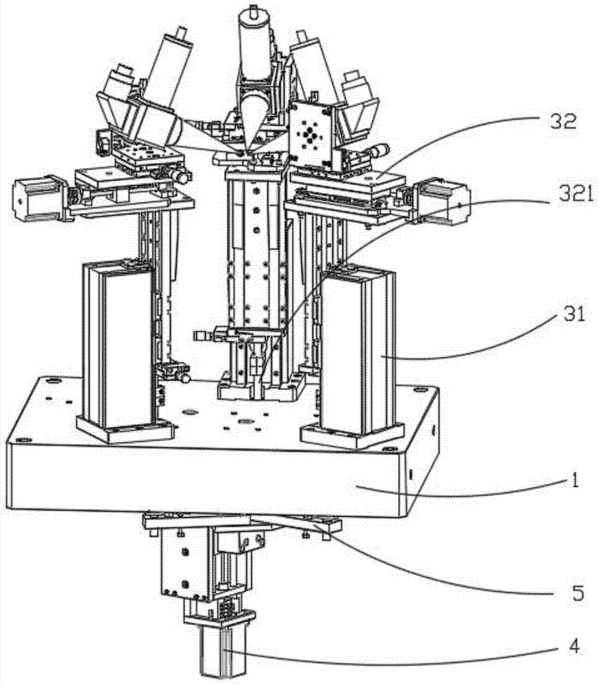
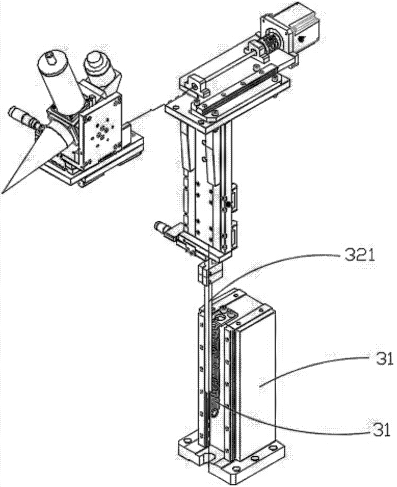
[0031] The coupling welding machine of the present invention includes several welding devices. The welding device includes a base body and a laser welding part that can slide up and down relative to the base body. The motor controls several laser welding parts at the same time, realizing the effect of keeping the height of the laser welding parts consistent. An elastic device is arranged between the laser welding part and the base part, so that the elastic force generated by the elastic device can balance the gravity on the laser welding part, so that a high-precision screw rod can be used to ensur...


PUM


Abstract

The invention is applicable to the field of optical devices and provides a coupling welding machine. The coupling welding machine comprises a supporting part, a coupling system and a plurality of welding devices. Each welding device comprises a base body part fixed to the supporting part and a laser welding part capable of moving up and down relative to the base body part. The coupling welding machine further comprises a motor. The motor can control a driving plate to move up and down through a lead screw. The laser welding parts are connected to the driving plate and can slide up and down along with motion of the driving plate. The laser welding parts are connected with elastic devices. Elastic force generated by the elastic devices can balance gravity borne by the laser welding parts. The coupling welding machine controls all the laser welding parts to slide up and down through the driving plate, and the effect of height consistence of the laser welding parts is achieved. Meanwhile, the elastic force generated by the elastic devices can balance the gravity borne by the laser welding parts. Thus, the high-precision lead screw can be adopted, and the up-down movement position precision of the laser welding parts is guaranteed.

Description

technical field [0001] The invention belongs to the field of optical devices, in particular to a coupling welding machine. Background technique [0002] With the continuous development of science and technology, communication technology is becoming more and more important in people's life, and people's increasing demand for communication has also made optical communication technology develop greatly. At present, in the field of communication technology, the application range of using optical transceiver modules to realize high-speed and large-capacity data transmission continues to expand, and more and more cables are replaced by high-speed lossless optical fibers. Existing light emitting and light receiving devices are made of semiconductor lasers or semiconductor light receivers through packaging technology into optical communication standard interface products. Optical transmitting devices can convert electrical signals into optical signals, and then connect with transmi...

Claims


Application Information

Patent Timeline
IPC IPC(8): B23K26/21B23K26/08B23K26/70
CPCB23K26/0853B23K26/0869B23K26/21B23K26/702
Inventor 王彦孚黄建业李若林
Owner 深圳市大族锐波传感科技有限公司
Why Eureka
Try Eureka