[0020] The following will clearly and completely describe the technical solutions in the embodiments of the present invention with reference to the accompanying drawings in the embodiments of the present invention. Obviously, the described embodiments are only some, not all, embodiments of the present invention. Based on the embodiments of the present invention, all other embodiments obtained by persons of ordinary skill in the art without making creative efforts belong to the protection scope of the present invention.
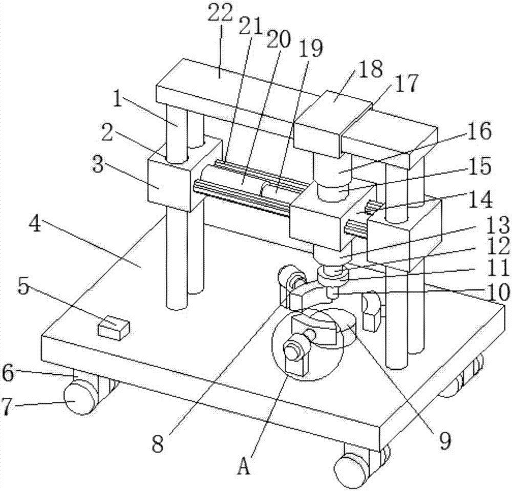
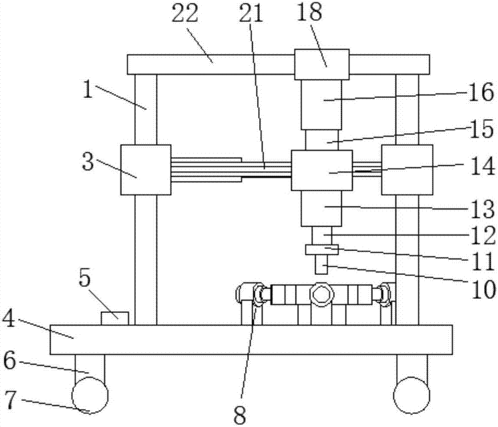
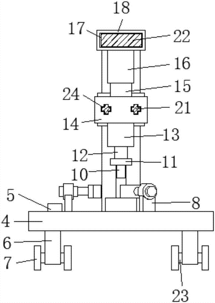
[0021] see Figure 1-4 , the present invention provides a technical solution: a NdFeB sheet cutting processing equipment, including a base plate 4, the lower surface of the base plate 4 is provided with support legs 6, the number of support legs 6 is four and arranged at equal intervals, the support legs 6 One end of the rotating rod 23 is provided with a rotating rod 23, and the two ends of the rotating rod 23 are provided with rollers 7, which is convenient for moving the device. The upper surface side of the base plate 4 is provided with a motor switch 5, and the input end of the motor switch 5 is electrically connected to the output end of the external power supply. Connect, the right side of the upper surface of the bottom plate 4 is provided with a clamp mechanism 8, the number of the clamp mechanism 8 is three and distributed in a circle, the clamp mechanism 8 includes a connecting plate 25, and one end of the connecting plate 25 is provided with a connecting ring 27, the connecting ring 27 is sleeved with a pneumatic cylinder 26, the pneumatic cylinder 26 is connected to the external air source pipeline, the pneumatic cylinder 26 is connected to the positioning clamping block 29 through the movable rod 28, and the positioning clamping block 29 is arc-shaped, which can quickly position and clamp the workpiece, reducing When used for manual positioning and clamping of the workpiece, the movable rod 28 is threadedly connected with the positioning clamping block 29, and the positioning clamping block 29 can be replaced to locate different workpieces. The right side of the upper surface of the base plate 4 is provided with a circular spacer 9, and the circular spacer 9 is located at the inner center of the fixture mechanism 8, and is used to place the workpiece. The upper surface of the bottom plate 4 is provided with four support columns 1, two support columns 1 on the left side and two support columns on the right side 1 are movably socketed with a first slider 3, the side surface of the first slider 3 is provided with a circular through hole 2 corresponding to the support column 1, and a slide rail 21 is provided between the two first sliders 3, The number of slide rails 21 is not less than two, and the number of slide rails 21 is not less than two, and the number of slide rails 21 is arranged at equal intervals. The slide rails 21 are cross-shaped slide rails. , the side surface of the second slider 14 is provided with through holes 24 corresponding to the slide rails 21, the number of the through holes 24 is not less than two, and the number of the through holes 24 is not less than two, and the through holes 24 are arranged at equal intervals. 24 is a cross-shaped through hole, and a telescopic structure is provided between the second slider 14 and the first slider 3. The telescopic structure includes a first hydraulic cylinder 20, and the first hydraulic cylinder 20 is connected to an external oil pipeline, and through the external oil pipeline The system controls the start and stop. The first hydraulic cylinder 20 is connected to the second slider 14 through the first movable rod 19. Through the first hydraulic cylinder 20, the first hydraulic cylinder 20 drives the second slider 14 to move along the slide rail 21. The second The slider 14 drives the tool 10 below to move, and the tops of the four supporting columns 1 are fixed with a flat plate 22, and the outer surface of the flat plate 22 is movably fitted with a sliding plate 18, and the side surface of the sliding plate 18 is provided with a through groove 17 corresponding to the flat plate 22. , one side of the slide plate 18 is fixed with a second hydraulic cylinder 16, the second hydraulic cylinder 16 is connected with the external oil pipeline, and the start and stop are controlled through the external oil circuit system, the second hydraulic cylinder 16 is connected with the second slider through the second movable rod 15 Block 14, a cutting mechanism is fixed on one side of the second slider 14, and the second hydraulic cylinder 16 works, and the second hydraulic cylinder 16 drives the second slider 14 to move, so that the first slider 3 moves along the support column 1, and the second hydraulic cylinder 16 moves along the support column 1. Two slide blocks 14 drive cutter 10 feed motions, and cutting mechanism comprises motor 13, and the input end of motor 13 is electrically connected with the output end of motor switch 5, and the output shaft of motor 13 is connected with by shaft coupling. Rotating shaft 12 is connected, and one end of rotating shaft 12 is provided with tool mount 11, and the side surface of cutter mount 11 is equipped with cutter 10, and changing cutter 10 can drill or grind workpiece, and is flexible in use and widely used.
[0022] When in use: put the workpiece on the circular pad 9, start the external air source, and the three pneumatic cylinders 26 work at the same time, the pneumatic cylinder 26 pushes the positioning and clamping block 29 to move through the movable rod 28, and quickly positions and clamps the workpiece. Turn on the external power supply, start the external oil circuit system, the first hydraulic cylinder 20 works, the first hydraulic cylinder 20 drives the second slider 14 to move along the slide rail 21 through the first movable rod 19, and the tool under the second slider 14 10 Align the workpiece, the second hydraulic cylinder 16 works, the second hydraulic cylinder 16 drives the second slider 14 to move downward through the second movable rod 15, at this time the first slider 3 moves downward along the support column 1, and the motor is started The switch 5, the motor 13 works, the motor 13 drives the rotating shaft 12 to rotate through the coupling, and then drives the tool 10 to feed and rotate the cutting workpiece. The tool can also be changed, and the workpiece can be ground and processed, and it can process workpieces of different sizes. It is widely used. .
[0023] The present invention is simple in structure and easy to use. The roller 7 under the support leg 6 is convenient for moving the device. The positioning and clamping block 29 is driven to move by the pneumatic cylinder 26 to quickly position and clamp the workpiece, reducing the time spent on manual positioning and clamping the workpiece. Working through the motor 13, the motor 13 drives the cutter 10 to rotate, and the cutter 10 can be replaced, and the workpiece can be drilled or ground. Through the first hydraulic cylinder 20, the first hydraulic cylinder 20 drives the second slider 14 to slide along the The rail 21 moves, and the second slider 14 drives the lower tool 10 to move, which is convenient for loading workpieces and can process workpieces of different sizes. The second hydraulic cylinder 16 works, and the second hydraulic cylinder 16 drives the second slider 14 to move, so that the first The first slider 3 moves along the support column 1, and the second slider 14 drives the cutting tool 10 to move, which is flexible and widely used.
[0024] Although the embodiments of the present invention have been shown and described, those skilled in the art can understand that various changes, modifications and substitutions can be made to these embodiments without departing from the principle and spirit of the present invention. and modifications, the scope of the invention is defined by the appended claims and their equivalents.