
Air-levitated train

A technology of air flotation and trains, which is applied in the field of rail transit, can solve pollution and other problems, and achieve the effects of low pollution, good stability and low cost

Inactive Publication Date: 2017-11-28
尚德敏 +2
View PDF0 Cites 1 Cited by
  • Summary
  • Abstract
  • Description
  • Claims
  • Application Information

AI Technical Summary

Problems solved by technology

[0008] Aiming at the various drawbacks of air-floating trains in Europe and America in history, in order to overcome their shortcomings in energy consumption, pollution and noise, the present invention provides an air-floating train powered by ground, driven by a vehicle-mounted motor, and suspended by a vehicle-mounted blower

Method used


Image

  • Air-levitated train
  • Air-levitated train
  • Air-levitated train

Examples


Embodiment Construction

[0036] The present invention will be described in further detail below in conjunction with the accompanying drawings and embodiments.

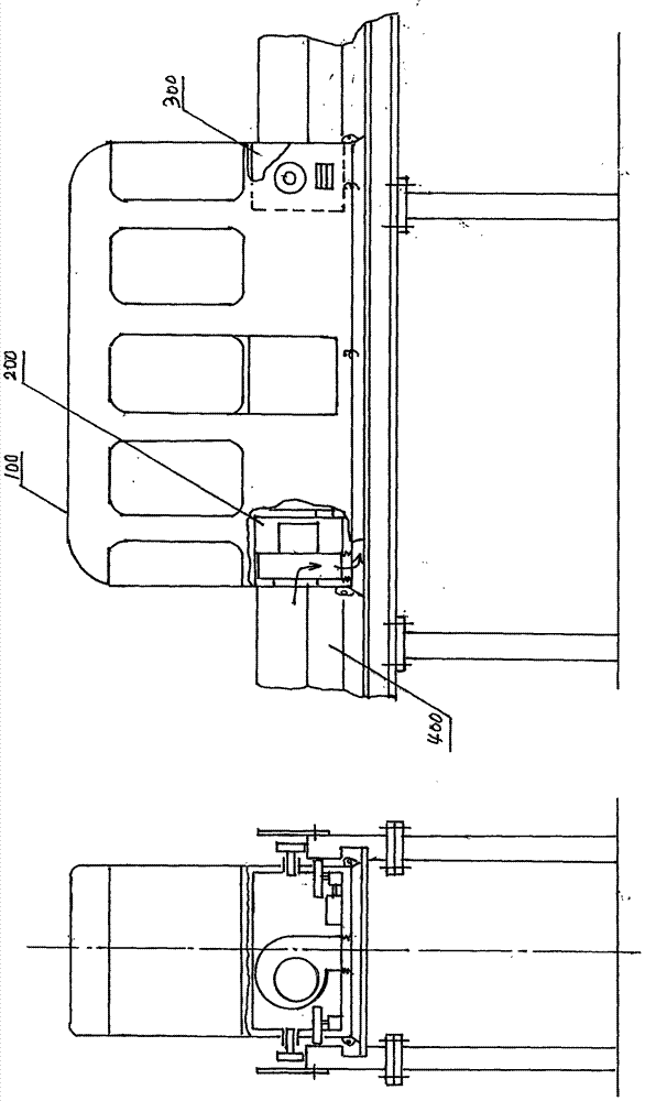
[0037] figure 1 The overall structure diagram of the embodiment of the air bearing train of the present invention is given.

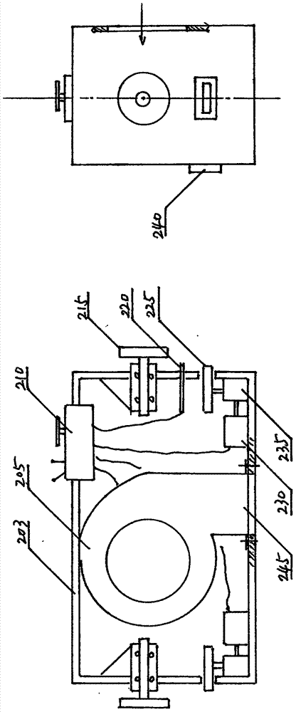
[0038] The overall structure of the embodiment of the air-floating train provided by the present invention is composed of multiple sections, and each section includes: an air-floating car 100 , a front power box 200 , a rear power box 300 , and a track device 400 .

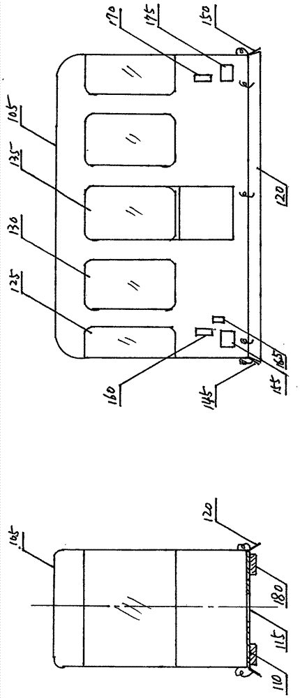
[0039] The air-floating carriage 100 is composed of a car body, a windshield, a vehicle window, a car door, a front tugboat opening, a front driving wheel opening, a pantograph opening, a front windshield, a side windshield, a rear windshield, a rear tugboat mouth and a rear drive wheel mouth composition.

[0040] The air flotation car 100 relies on the blower to provide high-pressure air, squeezes it into the bottom of the car, and forms an air cushion i...


PUM


Abstract

The present invention provides an air-floating train, which has multiple sections, and each section comprises: an air-floating carriage, a front power box, a rear power box and a track device. The front power box and the rear power box are respectively located at the front end and the rear end of the air-floating car. The front and rear power boxes respectively rely on wheels to walk on the track device and push the air-floating car forward and backward respectively. The front power box includes: front box body, pantograph, front controller, front AC motor, front commutator, front driving wheel, front tug wheel and blower. The pantograph is in sliding contact with the contact line on the track to obtain power, and the blower sucks in air from the outside, pressurizes it and introduces it under the floor of the air-floating car to form an air cushion, and the air cushion supports the air-floating car. The track device includes: baffle, track, bottom plate, column and contact line. The upper surface of the track is the tug wheel track, the inner side of the track is the driving wheel track, the transverse groove part is placed on the bottom plate, and on the inner surface of one side track, there is a contact Line, through the pantograph, to supply power to the air-floating train.

Description

technical field [0001] The invention relates to rail transit technology, in particular to an air-floating train. Background technique [0002] In traditional railways, the adhesion between the wheels and rails produces traction. When the speed of the train increases, the windward air resistance increases, but the adhesion decreases as the speed increases, so there is a limit to the speed of the adhesion railway. In order to break through this speed limit, and to completely overcome the problems of friction, vibration and instability between the wheels and rails of the sticking railway, in the 1970s, in Europe, America and Japan, two kinds of non-sticking air-floating trains appeared: Floating trains and Maglev trains. The air-floating train uses a gas engine to generate high-pressure gas, sprays it into the space between the vehicle and the guide rail to form an air cushion, and then uses a turbojet to drive the vehicle forward. The aerotrain developed by France reaches a ...

Claims


Application Information

Patent Timeline
IPC IPC(8): B60V3/04B60L13/00
CPCB60V3/04B60L13/006
Inventor 尚德敏尚尔海尚尔丽
Owner 尚德敏
Learn More