
Manufacturing technology for smectic phase liquid crystal product

A manufacturing process and smectic phase technology, applied in nonlinear optics, instruments, optics, etc., can solve problems such as inability to achieve smooth diffusion leveling, product size limitations, and inability to achieve precise control, so as to effectively guarantee product quality , Precise control of the process, and the effect that the product size is no longer limited

Inactive Publication Date: 2017-11-28
HALATION PHOTONICS CORP
View PDF7 Cites 1 Cited by
  • Summary
  • Abstract
  • Description
  • Claims
  • Application Information

AI Technical Summary

Problems solved by technology

It can be seen from the actual implementation that this heating filling process has the following disadvantages: First, since a large amount of mixed solution needs to be squeezed in from the filling port by pressure, it cannot be precisely controlled, the production efficiency is low, and the yield is limited.
Second, the consumption of smectic liquid crystals is large, resulting in serious waste
Third, the size of the product is greatly limited due to the heating process, usually only 1 hour to 20 hours of product can be produced
The high viscosity characteristics of smectic liquid crystals make it impossible to use in quantitative infusion equipment and vacuum lamination equipment operated at room temperature. The output usually needs to be controlled within 0.1mg, and such a small amount of control is impossible for high-viscosity smectic liquid crystals
In addition, on the vacuum lamination equipment at room temperature, the high-viscosity smectic liquid crystal cannot smoothly discharge the bubbles in it, and cannot smoothly diffuse and level the entire filling area.

Method used


Image

  • Manufacturing technology for smectic phase liquid crystal product
  • Manufacturing technology for smectic phase liquid crystal product

Examples


Embodiment Construction

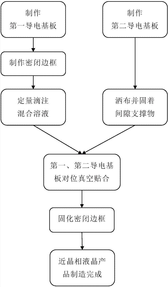
[0020] Such as figure 1 Shown, the manufacturing process of smectic phase liquid crystal product of the present invention comprises the steps:

[0021] 1) Make the first and second conductive substrates, wherein: the first base layer 10 and the conductive electrode layer 30 arranged thereon are the first conductive substrate, and the second base layer 20 and the conductive electrode layer 30 arranged thereon are the second conductive substrate;

[0022] 2) Execute the following steps 2-1) and steps 2-2) simultaneously or in parallel:

[0023] 2-1) Coating frame glue on the first conductive substrate to make a closed frame 50 (usually rectangular) without a filling port, quantitatively instilling a liquid mixed solution with reduced viscosity in the closed frame 50, wherein: mixing The solution is obtained by the transition of smectic liquid crystals in the liquid crystal mixture;

[0024] 2-2) Sprinkle the gap support 70 (micron-sized plastic balls or plastic rods, etc.) o...


PUM


Abstract

The invention discloses a manufacturing technology for a smectic phase liquid crystal product. The manufacturing technology comprises the followings steps of preparing a first and second conductive substrates, simultaneously executing the following two steps of coating side frame glue to the first conductive substrate to prepare a sealed side frame and dipping viscosity-reduced liquid-state mixed solution into the sealed side frame in a quantitative way, and spraying gap supporting articles on the second conductive substrate and enabling the gap supporting articles to be distributed and fixed on the second conductive substrate, heating the first and second conductive substrate, counter-pointing and applying the first and second conductive substrates in a vacuumized way after the viscosity of the liquid crystal-state mixture is reduced again, solidifying the sealed side frame, and accomplishing the manufacturing of the smectic phase liquid crystal product. Realization of the method is conducted via a low-viscosity and quantitative dipping way; the technology can be precisely controlled; high production efficiency and guaranteed product quality can be achieved; and the smectic phase liquid crystal consumption is little and the product size is free of limitations.

Description

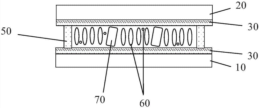
technical field [0001] The invention relates to a manufacturing process of a smectic liquid crystal product based on low-viscosity quantitative dripping, and belongs to the field of production technology of smectic liquid crystal products. Background technique [0002] The structure of existing smectic liquid crystal products is roughly as follows figure 2 As shown, it includes first and second base layers 10 and 20 , and conductive electrode layers 30 are provided on the inner surfaces of the first and second base layers 10 and 20 . The first base layer 10 and the conductive electrode layer 30 thereon form a first conductive substrate, and the second base layer 20 and the conductive electrode layer 30 thereon form a second conductive substrate. Between the first and second conductive substrates is a mixed layer 60 obtained by mixing smectic liquid crystals and conductive additives. The mixed layer 60 is doped with a gap support 70 (also known as a spacer), and the mixed la...

Claims


Application Information

Patent Timeline
Patent Type & Authority Applications(China)
IPC IPC(8): G02F1/1341
CPCG02F1/1341G02F1/13415
Inventor 周盼华吴立东孙刚
Owner HALATION PHOTONICS CORP
Learn More