Eureka AIR delivers breakthrough ideas for toughest innovation challenges, trusted by R&D personnel around the world.

Convex array probe clamping sleeve assembly and convex array probe assembly

A ferrule and component technology, which is applied in the field of medical ultrasonic convex array probe detection, can solve the problems of poor patient comfort, lack of coupling effect, stickiness, etc., and achieve the effects of falling protection and improving the sense of experience

Active Publication Date: 2017-12-01
SHENZHEN MINHAO TECH CO LTD
View PDF7 Cites 11 Cited by
  • Summary
  • Abstract
  • Description
  • Claims
  • Application Information

AI Technical Summary

Problems solved by technology

[0002] In the existing ultrasonic testing involving convex array probes, viscous liquid couplants are often applied to the human body testing site. The disadvantages are: sticky, greasy, and poor patient comfort
In addition, the couplant needs to be replenished repeatedly during long-term ultrasound operations; when liquid couplant is used for superficial skin tissue, concave-convex parts, etc. during detection or treatment, the desired coupling effect is usually not achieved, and the coupling image is blurred
The use of traditional liquid coupling agents not only contains a large amount of oil and chemical solvents, but also often leads to corrosion and cracking of the acoustic lens, resulting in loss

Method used


Image

  • Convex array probe clamping sleeve assembly and convex array probe assembly
  • Convex array probe clamping sleeve assembly and convex array probe assembly
  • Convex array probe clamping sleeve assembly and convex array probe assembly

Examples


Embodiment 1

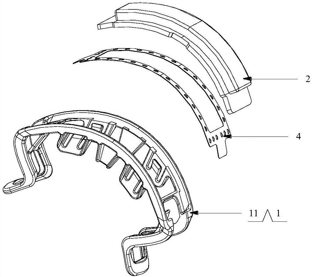
[0029] refer to Figure 3 to Figure 4 , as a preferred embodiment, wherein:

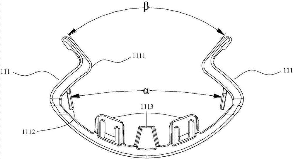
[0030] The two Z-shaped components 111 are arranged mirror-symmetrically.

[0031] Each Z-shaped member also extends a suspended first stopper 1112 between the two bent ends, and the two first stoppers 1112 of the two Z-shaped members are used to limit the relative distance between the two sides of the convex array probe in the length direction. slide. The angle α formed by the two first limiting portions 1112 is 0°˜60°.

[0032] The two Z-shaped components 111 are hollowed out with second limiting parts 1113 on both sides of the common bottom end to limit the relative sliding of the two sides in the width direction of the convex array probe.

[0033] The angle β formed by the two tops of the two Z-shaped members 111 is 30°-90°.

[0034] In Embodiment 1, based on this structure, the external solid-state medical ultrasonic coupling patch can be limited between the convex array probe and the ferrul...

Embodiment 2

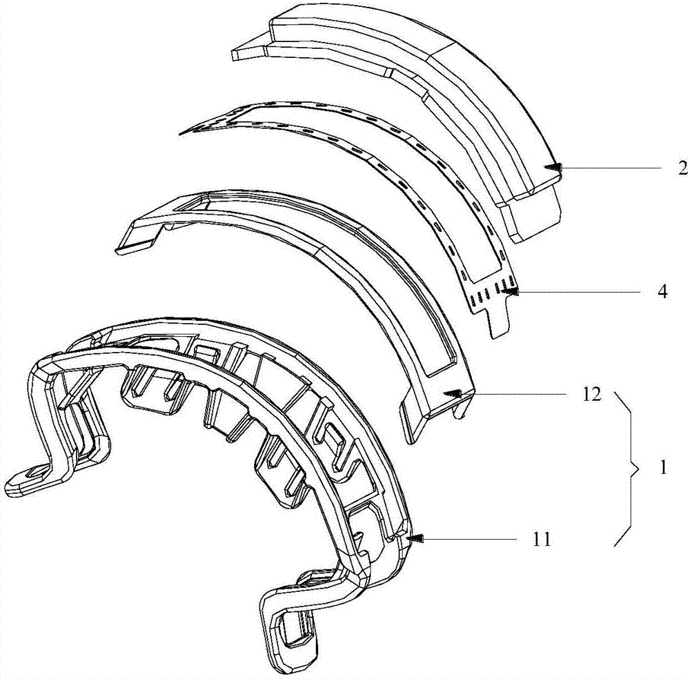
[0036] refer to Figure 5 , as another preferred embodiment, on the basis of Embodiment 1, the ferrule also includes an arc-shaped gland 12, which is fastened on the hollow bottom end of the ferrule body 11 to clamp the external solid Medical Ultrasound Coupling Patch 2. For the convenience of operation, the arc-shaped gland 12 is fastened on the outer side of the hollow common bottom end of the ferrule body. Embodiment 2 provides another fastening method of the coupling patch 2, which is sequentially fastened to the bottom of the hollowed-out joint from the outside. This method is relatively easy to operate and has a better effect.

[0037] refer to Image 6 , In addition, the present invention also provides a convex array probe assembly, including: a convex array probe 3, and the above ferrule assembly, the head end of the convex array probe 3 is engaged with the ferrule assembly.


PUM


Abstract

The invention discloses a convex array probe clamping sleeve assembly and a convex array probe assembly. The clamping sleeve assembly includes a clamping sleeve and a solid medical ultrasonic coupling patch; the clamping sleeve is used for clamping the solid medical ultrasonic coupling patch so as to allow an external convex probe to contact a surface of the solid medical ultrasonic coupling patch; the other surface of the solid medical ultrasonic coupling patch faces outward and is used for detection. The solid medical ultrasonic coupling patch can be clamped on the convex array probe; the solid medical ultrasonic coupling patch is used in ultrasonic operation, an output ultrasonic image is clear in a far-field end, an intermediate-field end, and a near-field end; when the solid medical ultrasonic coupling patch is used, the conventional liquid coupling agent can be avoided, and the user experience is improved. The ultrasonic coupling patch is solid and flexible, and is flat and glossy in surface; a moisture retaining liquid adheres to a surface of a solid gel tablet, the surface pH is neutral, and probe sound lens corrosion or rupture can be avoided; the clamping sleeve can protect the probe from falling.

Description

technical field [0001] The invention relates to the detection of a medical ultrasonic convex array probe, in particular to a convex array probe ferrule assembly and a convex array probe assembly. Background technique [0002] In the existing ultrasonic detection involving convex array probes, viscous liquid couplant is often applied to the detection site of the human body. The disadvantages are: sticky, greasy, and poor patient comfort. In addition, the couplant needs to be replenished repeatedly during long-term ultrasound operations; during detection or treatment, when liquid couplant is used for superficial skin tissue, concave-convex parts, etc., the desired coupling effect is usually not achieved, and the coupled image is blurred. The use of traditional liquid coupling agents not only contains a large amount of oil and chemical solvents, but also often leads to corrosion and cracking of the acoustic lens, resulting in loss. The patent CN 201610005786.5 previously appli...

Claims


Application Information

Patent Timeline
Patent Type & Authority Applications(China)
IPC IPC(8): A61B8/00A61B50/30
CPCA61B8/4455A61B50/30A61B8/4281A61B8/4272
Inventor 钟以聪
Owner SHENZHEN MINHAO TECH CO LTD
Why Eureka
Eureka Blog
Learn More