Wire drawing machine and machining method thereof

A wire drawing machine and wire drawing technology, applied in metal processing equipment, manufacturing tools, grinding workpiece supports, etc., can solve problems such as low wire drawing efficiency, uneven lines, inconsistent line depth, etc., to ensure processing quality, reliability, The effect of high wire drawing efficiency

Pending Publication Date: 2017-12-01
珠海桑贝思精密科技有限公司
View PDF9 Cites 4 Cited by
  • Summary
  • Abstract
  • Description
  • Claims
  • Application Information

AI Technical Summary

Problems solved by technology

However, because the abrasive cloth or sandpaper is extremely easy to wear and tear, it needs to be replaced continuously, resulting in production suspension and affecting production efficiency
Moreover, most of the traditional wire drawing processing of mobile phone cases is realized by manual operation, and the uneven force control of manual wire drawing can easily lead to problems such as the texture layout, uneven texture and inconsistent texture depth of the mobile phone case.
At the same time, when manual wire drawing is used, it is impossible to perform wire drawing operations on curved products or special-shaped products
In addition, manual wire drawing has disadvantages such as high labor intensity, high labor cost, poor wire drawing effect, low product yield and low wire drawing efficiency.

Method used


Image

  • Wire drawing machine and machining method thereof
  • Wire drawing machine and machining method thereof
  • Wire drawing machine and machining method thereof

Examples


Embodiment Construction

[0032] Drawing machine embodiment:

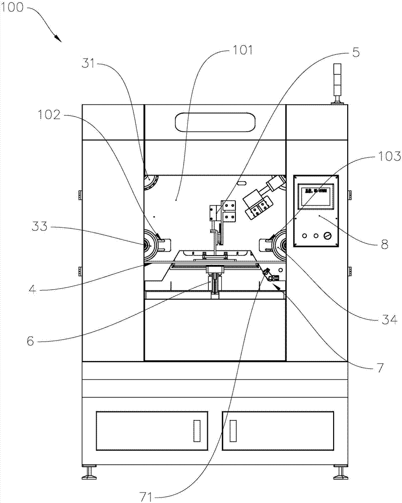
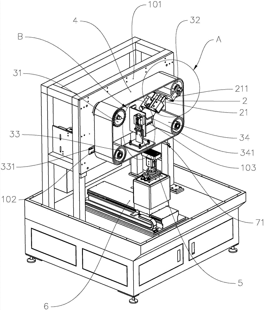
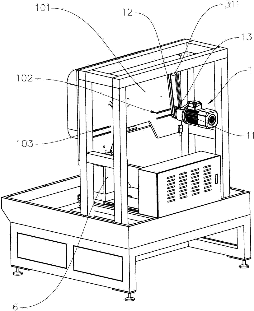
[0033] refer to Figure 1 to Figure 3 , the wire drawing machine 100 includes a frame 101 , a first driving mechanism 1 , a second driving mechanism 2 , a plurality of rollers, a wire drawing belt 4 , a pressing device 5 , a clamping device 6 , a cooling device 7 and a control system 8 . Wherein, a plurality of roller axes are not on the same straight line.

[0034] Preferably, the number of roller shafts is four, and the first roller shaft 31 is rotatably connected with the frame 101 around its own axis, and the second roller shaft 32 is rotatably connected with the driving end of the second drive mechanism 2 around its own axis. The third roller shaft 33 is rotatably connected to the frame 101 around its own axis, and the fourth roller shaft 34 is rotatably connected to the frame 101 around its own axis. The drawing ribbon 4 is respectively adjacent to the four rollers, and the drawing ribbon 4 is wound around the four rollers.

[0035...


PUM


Abstract

The invention provides a wire drawing machine and a machining method thereof. The wire drawing machine comprises a machine frame, a first driving mechanism, a second driving mechanism, a plurality of roll shafts, a wire drawing belt, a downward pressing device and a fixture device. The first driving mechanism and the second driving mechanism are fixedly connected with the machine frame. The first roll shaft is connected with the machine frame, and the first driving mechanism drives the first roll shaft to rotate. The second roll shaft is rotationally connected with the second driving mechanism, and the second driving mechanism drives the second roll shaft to move in the axial direction of the second driving mechanism. The third roll shaft is connected with the machine frame. The wire drawing belt is wound on the multiple roll shafts. The downward pressing device comprises a third driving mechanism and a downward pressing assembly. The fixture device comprises a tool fixture, the tool fixture and the downward pressing assembly are located on the two sides of the wire drawing belt correspondingly, the tool fixture is opposite to the downward pressing assembly, and the third driving mechanism drives the downward pressing assembly to push the wire drawing belt towards the tool fixture. The invention further provides the machining method of the wire drawing machine. The wire drawing machine and the machining method thereof have the advantages of being good in wire drawing effect and high in wire drawing quality and wire drawing efficiency.

Description

technical field [0001] The invention relates to the technical field of mechanical equipment, in particular to a wire drawing machine and a processing method of the wire drawing machine. Background technique [0002] With the popularization of mobile phones, people attach great importance to the appearance of mobile phones in addition to the performance requirements of mobile phones. For mobile phones with metal shells, the metal surface is often brushed to make directional stripes on the surface of the metal back shell of the mobile phone, so as to increase the texture and appearance of the metal shell. In the existing technology, the abrasive cloth or sandpaper is usually laid flat and then fixed, and the metal back shell is polished back and forth on the abrasive cloth or sandpaper to form a wire drawing effect. However, since the abrasive cloth or sandpaper is very easy to wear and tear, it needs to be replaced continuously, resulting in suspension of production and affe...

Claims


Application Information

Patent Timeline
Patent Type & Authority Applications(China)
IPC IPC(8): B24B21/04B24B47/12B24B21/20B24B41/06B24B21/06B24B55/02B24B55/08B24B51/00
CPCB24B21/04B24B21/06B24B21/20B24B41/06B24B47/12B24B51/00B24B55/02B24B55/08
Inventor 何林鲁秋瑞
Owner 珠海桑贝思精密科技有限公司
Why Eureka
Try Eureka