APU system module cooling device and method

A system module and cooling device technology, which is applied in the field of APU system module cooling device, can solve the problems of slow engine heating, high noise, too much engine limitation, etc., and achieve the effect of improving efficiency and reducing power consumption

Inactive Publication Date: 2017-12-01
SINO TRUK JINAN POWER
View PDF4 Cites 10 Cited by
  • Summary
  • Abstract
  • Description
  • Claims
  • Application Information

AI Technical Summary

Problems solved by technology

[0002] At present, the auxiliary power unit of the automobile, that is, the APU system, generally adopts a mechanical cooling method. In this cooling method, the speed of the fan and water pump is affected by the speed of the engine, which is likely to cause poor heat dissipation at low speeds, and overheating of the engine in winter. Waiting for failures. In addition, this mechanical cooling method is too limited by the engine, so it can only be arranged at the front end of the engine pulley, which greatly restricts the layout of the vehicle. In addition, this cooling method also has the disadvantages of high noise and high power consumption.

Method used


Image

  • APU system module cooling device and method
  • APU system module cooling device and method

Examples


Embodiment 1

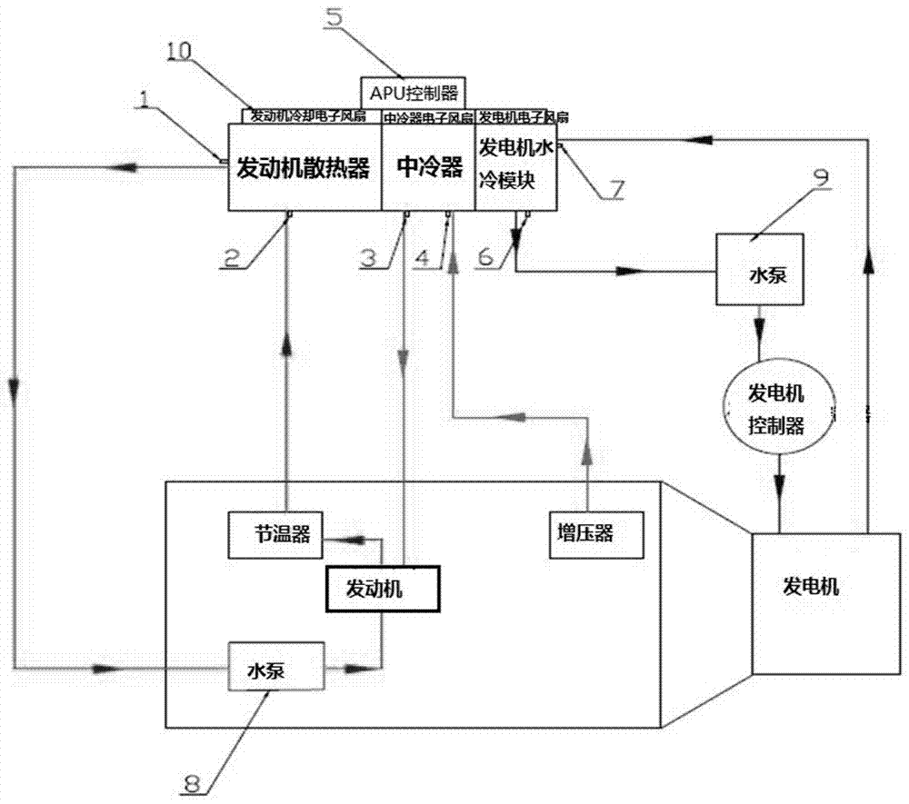
[0018] Such as figure 1 As shown, a cooling device for an APU system module, the APU system includes an engine, a supercharger, a thermostat, a water pump and a generator, and the cooling device includes an engine cooling water circuit, an engine intake cooling air circuit, a generator cooling Waterway and APU controller 5, the engine cooling waterway includes engine radiator and engine cooling electronic fan, the water inlet of the engine radiator is connected with the thermostat, the water outlet of the engine radiator is connected with the water pump, and the engine is connected with the water pump and the thermostat Between, the water inlet and the water outlet of the engine radiator are respectively provided with the engine inlet water temperature sensor 2 and the engine outlet water temperature sensor 1, and the engine cooling electronic fan, the engine inlet water temperature sensor 2 and the engine outlet water temperature sensor 1 are respectively controlled with the A...

Embodiment 2

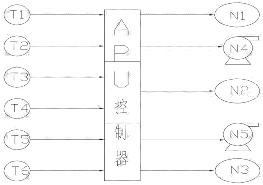
[0023] This embodiment discloses a cooling method for an APU system module, such as figure 1 Shown is the control principle diagram of this method. The cooling method is based on the cooling device described in Embodiment 1, S01), engine water cooling, the APU controller monitors the engine outlet water temperature through the engine outlet water temperature sensor, and adjusts the engine through hierarchical control. Cool the speed of the electronic fan and water pump so that the engine is in the best working condition; S02), the engine is air-cooled, the APU controller detects the intake air temperature of the intercooler through the intercooler intake temperature sensor, and adjusts the intercooler through hierarchical control The speed of the electronic fan of the generator can reduce the intake temperature of the engine when the engine is working at low speed, and improve the efficiency of the engine; S03), the generator is water-cooled, the APU controller monitors the mot...


PUM


Abstract

The invention discloses an APU system module cooling device and a method. The cooling device comprises an engine cooling water circuit, an engine intake cooling air circuit and an engine cooling water circuit, and the three cooling modules are of independence and noninterference; in addition, a traditional mechanical water pump is changed to a controllable water pump, so that the power consumption of a cooling system under the low speed working condition of an APU assembly is reduced; a traditional mechanical fan is changed to an electronic fan which is controlled in a blocking manner; the series connection of traditional cooling modules is changed into parallel connection, and the cooling modules are additionally provided with water inlet and outlet temperature sensors and air inlet and outlet temperature sensors; the traditional mechanical water pump is changed to the controllable electronic water pump and an electric control silicone oil pump. The cooling method is used for separately controlling engine cooling, engine intake cooling and generator cooling, and the speed of the electronic fan and the water pump is controlled by a control unit through the temperature sensors, and the system is controlled within the optimal working temperature range.

Description

technical field [0001] The invention relates to an APU system module cooling device and method, belonging to the technical field of automobiles. Background technique [0002] At present, the auxiliary power unit of the automobile, that is, the APU system, generally adopts a mechanical cooling method. In this cooling method, the speed of the fan and water pump is affected by the speed of the engine, which is likely to cause poor heat dissipation at low speeds, and overheating of the engine in winter. Waiting for failure. In addition, this mechanical cooling method is too limited by the engine, so it can only be arranged at the front end of the engine pulley, which greatly restricts the layout of the vehicle. In addition, this cooling method also has the disadvantages of high noise and high power consumption. Contents of the invention [0003] The technical problem to be solved by the present invention is to provide an APU system module cooling device and method, in which en...

Claims


Application Information

Patent Timeline
Patent Type & Authority Applications(China)
IPC IPC(8): F01P7/16F01P7/04F02B29/04B60K1/00B60K11/02B60K11/04
CPCB60K1/00B60K11/02B60K11/04B60K2001/003F01P7/04F01P7/164F01P2025/08F01P2025/50F01P2050/24F02B29/04F02B29/0431Y02T10/12
Inventor 白立柱郭瑞
Owner SINO TRUK JINAN POWER
Why Eureka
Try Eureka