3D printer planar motion precision measuring device
A 3D printer and plane motion technology, which is applied to measurement devices, optical devices, instruments, etc., can solve the problems of not satisfying the motion accuracy measurement of 3D printers, single functions of laser interferometers and laser trackers, etc. The effect of high measurement accuracy and convenient use
- Summary
- Abstract
- Description
- Claims
- Application Information
AI Technical Summary
Problems solved by technology
Method used
Image

Examples
Embodiment Construction
[0015] The present invention will be further described below according to the accompanying drawings and in conjunction with the embodiments.
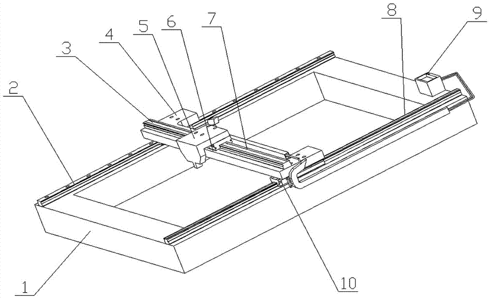
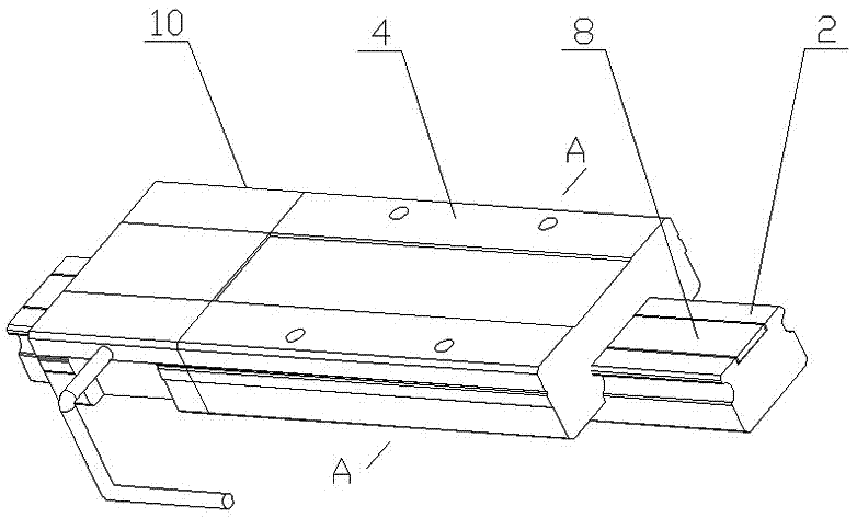
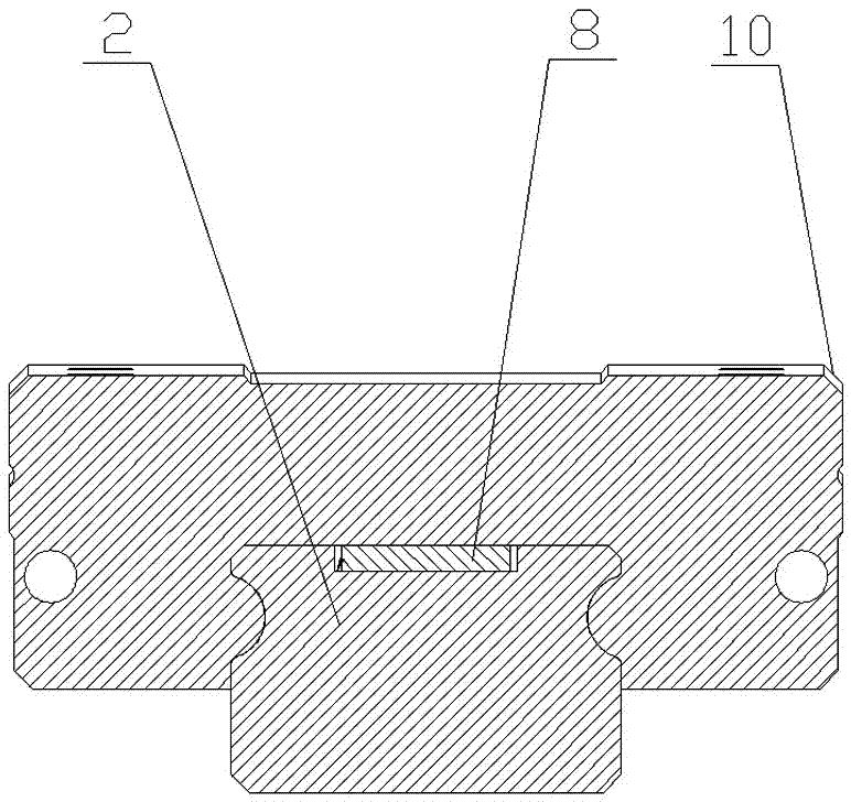
[0016] figure 1 The shown 3D printer planar motion accuracy measurement device includes a base 1, an X-direction rail 2, a Y-direction rail 3, an X-direction slide plate 4, a Y-direction slider 5, a Y-direction grating reading head 6, a Y-direction grating ruler 7, An X-direction grating ruler 8 , a data processing system 9 and an X-direction grating reading head 10 . The base 1 is a basic component, which is a flat rectangular frame, and a pair of X-guiding rails 2 parallel to each other are placed on the planes of the two long sides, and a rectangular groove is arranged in the center of the top surface of the X-guiding rail 2 to be embedded in the X-direction. Grating ruler 8. The X-direction slide plate 4 slides freely across the two X-direction guide rails 2 , and for the convenience of measurement, an X-direction grating reading ...
PUM
 Abstract
Description
Claims
Application Information