Boost power factor correction converter

A power factor correction and converter technology, which is applied in conversion devices and instruments that convert DC power input into DC power output and output power, can solve the problem of voltage stress of power switch tubes, and the difficulty of selecting power switch tubes and increase the number of power switch tubes. Switching loss and on-state loss, can not be widely used in practical occasions, etc., to achieve the effect of improving device utilization, reducing switching loss and on-state loss, and facilitating model selection

Active Publication Date: 2017-12-01
南京凌鸥创芯电子有限公司
View PDF11 Cites 4 Cited by
  • Summary
  • Abstract
  • Description
  • Claims
  • Application Information

AI Technical Summary

Problems solved by technology

In this way, on the one hand, the switching loss and on-state loss of the power switch tube are increased; on the other hand, the high voltage stress of the power switch tube brings difficulties to the selection of the power switch

Method used


Image

  • Boost power factor correction converter
  • Boost power factor correction converter
  • Boost power factor correction converter

Examples


Embodiment Construction

[0045] The following will clearly and completely describe the technical solutions in the embodiments of the present invention with reference to the drawings in the embodiments of the present invention. Apparently, the described embodiments are only some of the embodiments of the present invention, not all of them. The components of the embodiments of the invention generally described and illustrated in the figures herein may be arranged and designed in a variety of different configurations.

[0046] Accordingly, the following detailed description of the embodiments of the invention provided in the accompanying drawings is not intended to limit the scope of the claimed invention, but merely represents selected embodiments of the invention. Based on the embodiments of the present invention, all other embodiments obtained by those skilled in the art without making creative efforts belong to the protection scope of the present invention.

[0047] It should be noted that like nume...


PUM


Abstract

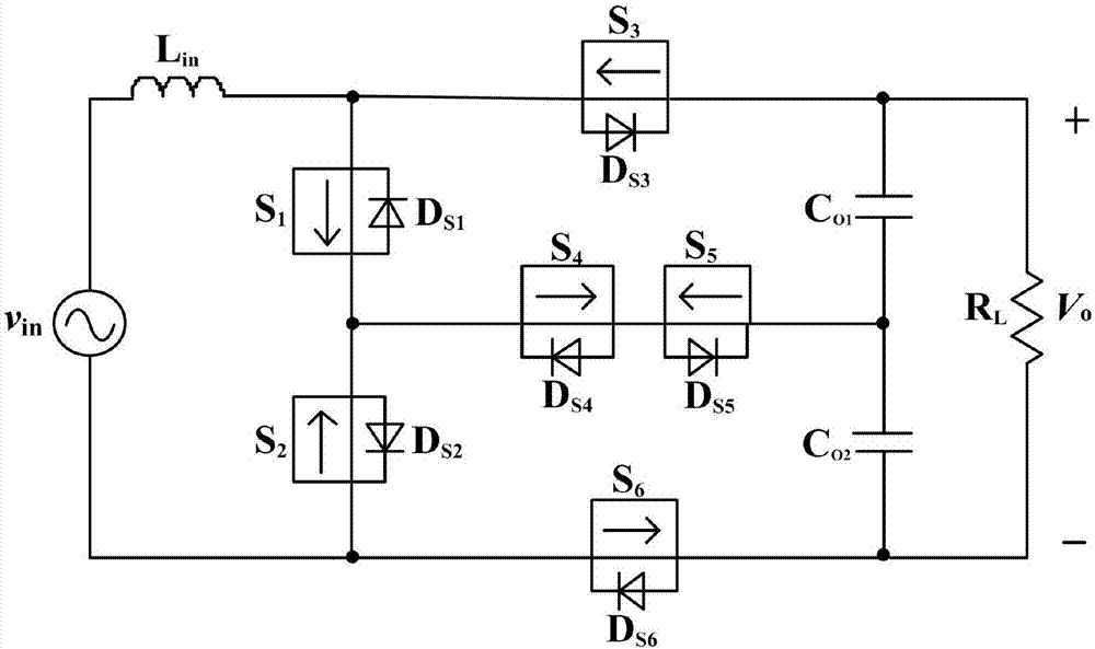
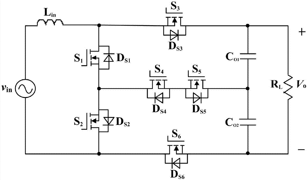
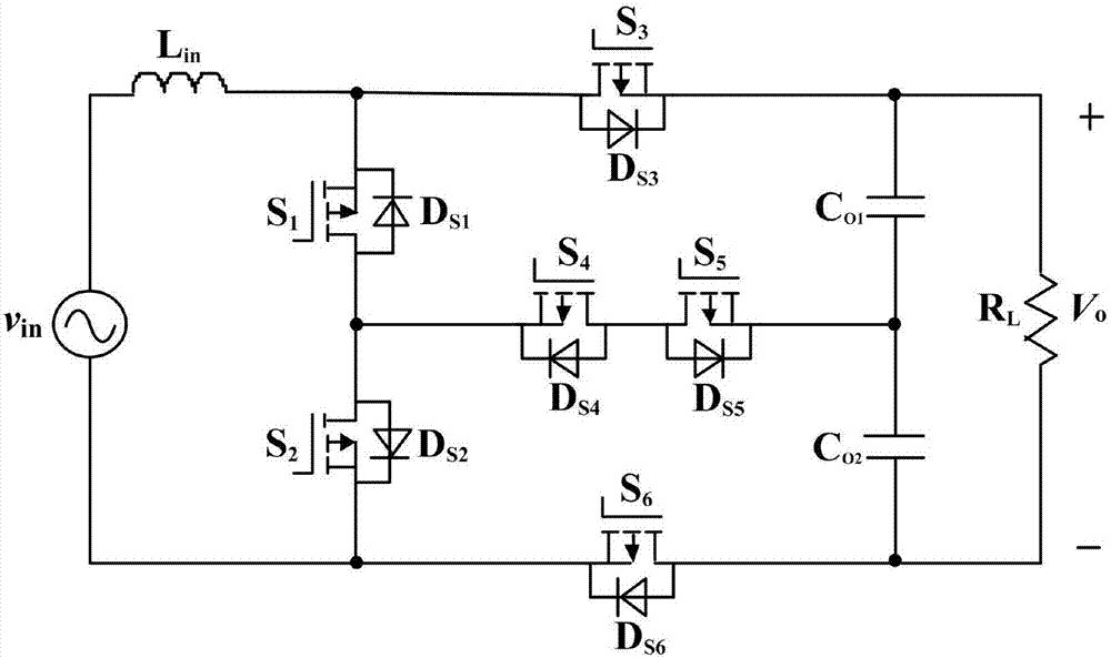
The invention relates to the technical field of electric energy conversion, and particularly, relates to a Boost power factor correction converter. The Boost power factor correction converter provided by the invention can achieve a power factor correction function under positive and negative input voltage conditions without a diode-bridge rectifier by controlling on-off states of a first power switch tube, a second power switch tube, a third power switch tube, a fourth power switch tube, a fifth power switch tube and a sixth power switch tube, has a small volume, reduces conduction loss and improves a device utilization rate. Moreover, the Boost power factor correction converter provided by the embodiment of the invention adopts a three-level topological structure, thereby effectively reducing voltage stresses of the first power switch tube, the second power switch tube, the third power switch tube, the fourth power switch tube, the fifth power switch tube and the sixth power switch tube, facilitating selection of the power switch tubes and reduction of switching loss and conduction loss, improving an output voltage level and the like.

Description

technical field [0001] The invention relates to the technical field of electric energy conversion, in particular to a Boost power factor correction converter. Background technique [0002] With the development of power electronics technology, the requirements for input current harmonics and input power factor in power conversion devices are getting higher and higher, and power factor correction converters have been widely used. Because of its continuous input current, simple topology and high efficiency, Boost circuit is the most widely researched and applied topology in active power factor correction converters. The Boost circuit is a unipolar gain DC / DC converter, which needs to be combined with a rectifier circuit to form a traditional Boost power factor correction converter. Due to the large conduction loss of the diode rectifier bridge, it accounts for about 30% to 60% of the loss of the traditional Boost power factor correction converter. With the increase of the inp...

Claims


Application Information

Patent Timeline
IPC IPC(8): H02M1/42H02M3/158
CPCH02M1/4225H02M3/1584Y02B70/10Y02P80/10
Inventor 李鹏王勇博
Owner 南京凌鸥创芯电子有限公司
Why Eureka
Try Eureka