
hydraulic pump

A technology of hydraulic pump and rotating shaft, applied in the field of hydraulic pump, can solve the problems of wear and tear of pre-pressure applying parts, and achieve the effect of inhibiting wear and tear

Active Publication Date: 2019-11-08
TOYOTA IND CORP
View PDF9 Cites 1 Cited by
  • Summary
  • Abstract
  • Description
  • Claims
  • Application Information

AI Technical Summary

Problems solved by technology

[0004] Here, in the hydraulic pump having the above-mentioned bearing structure, there is a problem that the preload applying member wears due to the high-speed rotation of the rotating shaft, and the target member that the preload applying member contacts rotates at a high speed.

Method used


Image

  • hydraulic pump
  • hydraulic pump
  • hydraulic pump

Examples


Embodiment Construction

[0017] Embodiments for implementing the present invention will be described in detail below with reference to the drawings. In addition, the same code|symbol is attached|subjected to the same or an equivalent member, and when the content to explain overlaps, this description is abbreviate|omitted.

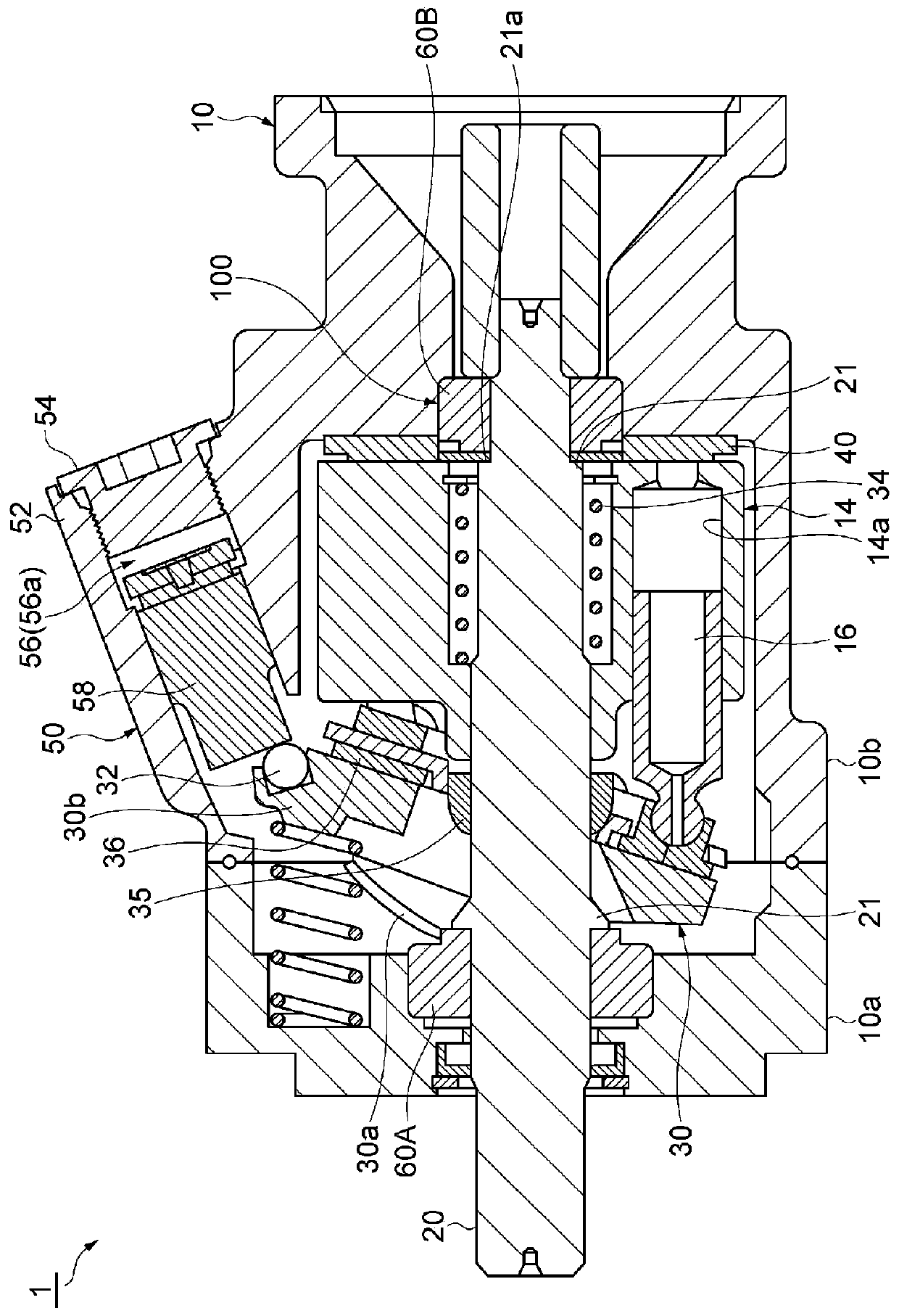
[0018] First, the configuration of the hydraulic pump of the present embodiment will be described. As an example of a hydraulic pump, see figure 1 The variable displacement piston pump (hereinafter simply referred to as hydraulic pump) 1 will now be described.

[0019] The hydraulic pump 1 includes: a pump housing 10 (housing), a rotating shaft 20 supported rotatably by the pump housing 10 and having a protruding end portion protruding from the pump housing 10, having a plurality of cylinder holes 14a in the circumferential direction of the rotating shaft 20, and The cylinder block 14 integrally rotating with the rotating shaft 20, the piston 16 provided slidably in the plurality...


PUM


Abstract

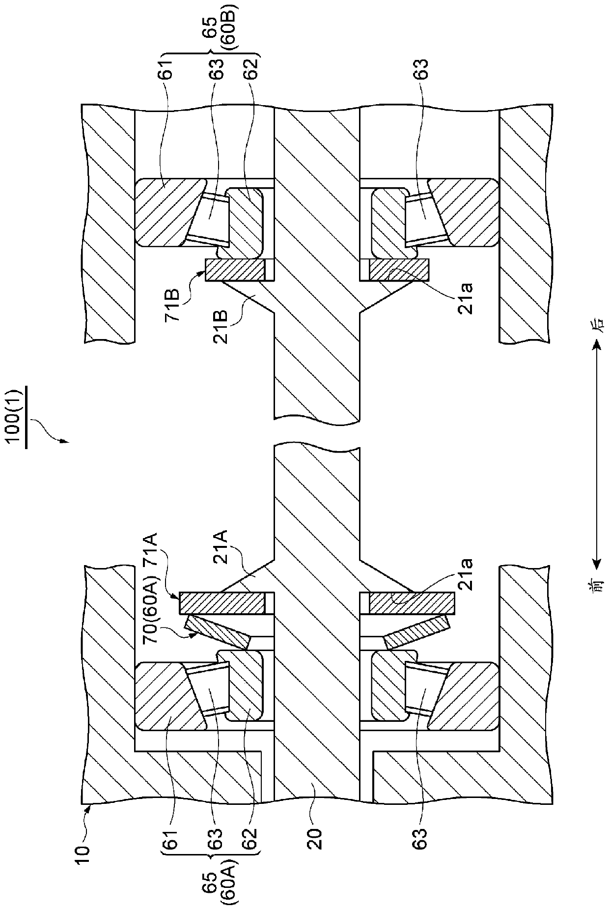
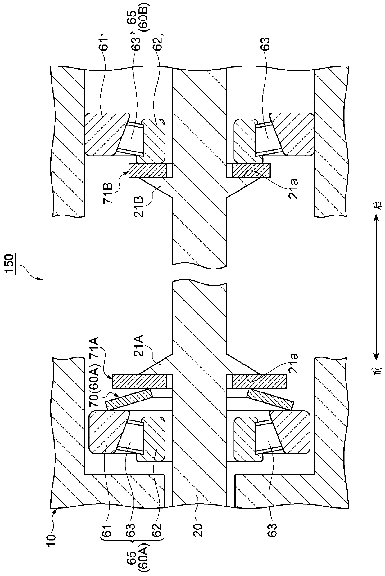
The present invention provides a hydraulic pump having a rotating shaft supported so as to be rotatable relative to a housing, the hydraulic pump comprising: bearings provided on one end side and the other end side of the rotating shaft, at least one of the sides is a first annular member provided around the rotation shaft, the bearing portion on one side has a support portion for rotatably supporting the rotation shaft, and a preload applying member for applying a preload in the axial direction to the support portion, In the axial direction, a first annular member is interposed between the one bearing portion and the support seat of the rotary shaft, and the inner diameter of the first annular member is larger than the diameter of the rotary shaft.

Description

technical field [0001] The present invention relates to a hydraulic pump provided with a bearing structure. Background technique [0002] Conventionally, as a hydraulic pump, there is known a variable displacement pump in which the discharge amount of the pump is changed by changing the inclination angle of the swash plate. For example, Patent Document 1 below describes a variable displacement pump including a rotating shaft and a cylinder block connected to the rotating shaft to rotate integrally, and pistons are reciprocally accommodated in a plurality of bores formed in the cylinder block. Furthermore, in the variable displacement pump described in Patent Document 1, the rotating shaft is supported by the housing via a pair of tapered roller bearings. In such a variable displacement pump, in order to ensure the bearing life of the tapered roller bearing supporting the rotating shaft, a preload applying member such as a disc spring is generally inserted between the rotati...

Claims


Application Information

Patent Timeline
Patent Type & Authority Patents(China)
IPC IPC(8): F04B1/22F16C25/08
CPCF04B1/2085F16C25/083F16C19/364F16C19/547F16C2360/42F04B53/00F16C25/08F04B1/2064F04B1/128F04B1/22F05B2210/11
Inventor 松尾力横町尚也上田祐规宇野峰志
Owner TOYOTA IND CORP
Learn More