
Sintered body for forming rare-earth magnet, and rare-earth sintered magnet

A technology of sintered body and magnet, applied in the direction of magnetic objects, magnetic materials, permanent magnets, etc., can solve the problems of unmanufacturability and the degree of deviation

Active Publication Date: 2017-12-01
NITTO DENKO CORP
View PDF17 Cites 2 Cited by
  • Summary
  • Abstract
  • Description
  • Claims
  • Application Information

AI Technical Summary

Problems solved by technology

The magnet produced by the method described in Patent Document 9 has a structure in which the axis of easy magnetization is oriented along one direction, and this method cannot produce a single sintered magnet in which magnet material particles in arbitrary multiple regions have different magnetic properties. orientation of the magnet
In addition, Patent Document 9 does not discuss how much the orientation given to each magnet material particle deviates from the intended orientation direction.

Method used


Image

  • Sintered body for forming rare-earth magnet, and rare-earth sintered magnet
  • Sintered body for forming rare-earth magnet, and rare-earth sintered magnet
  • Sintered body for forming rare-earth magnet, and rare-earth sintered magnet

Examples


Embodiment approach

[0068] Hereinafter, embodiments of the present invention will be described with reference to the drawings.

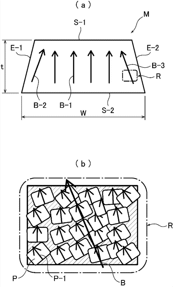
[0069] exist Figure 4 ~ Figure 7 An example of an electric motor incorporating a sintered body for forming a rare-earth magnet according to another embodiment of the present invention and a permanent magnet formed from the sintered body is shown in . The sintered body 1 for forming a rare-earth magnet contains a Nd—Fe—B-based magnet material as a magnet material. Here, as the Nd-Fe-B-based magnet material, for example, one containing R (R is one or two or more rare earth elements containing Y) in a ratio of 27.0 wt% to 40.0 wt% in weight percentage can be cited. , B is contained in a ratio of 0.6 wt % to 2 wt %, and Fe is contained in a ratio of 60 wt % to 75 wt %. Typically, the Nd-Fe-B magnet material contains Nd at a ratio of 27 wt % to 40 wt %, B at a ratio of 0.8 wt % to 2 wt %, and Fe as electrolytic iron at a ratio of 60 wt % to 75 wt %. For the purpose of im...

Embodiment 1

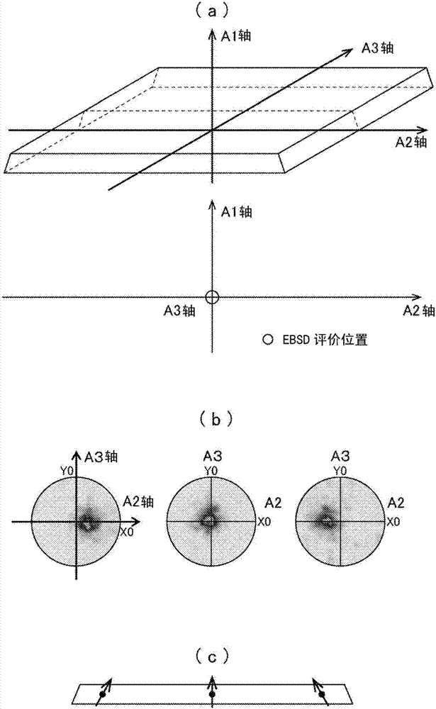
[0130] Made in the following order Figure 4 A rare earth sintered magnet of the shape shown.

[0131]

[0132] At room temperature, hydrogen is stored in the alloy obtained by the strip casting method (containing Nd: 25.25wt%, Pr: 6.75wt%, B: 1.01wt%, Ga: 0.13wt%, Nb: 0.2wt%, Co : 2.0wt%, Cu: 0.13wt%, Al: 0.1wt%, the remainder being Fe, and other unavoidable impurities) was kept at 0.85MPa for 1 day. Thereafter, hydrogen fragmentation was carried out by maintaining at 0.2 MPa for 1 day while cooling with liquefied Ar.

[0133]

[0134] After mixing 1 part by weight of methyl hexanoate with 100 parts by weight of the coarsely pulverized alloy powder, it was pulverized by a helium jet mill pulverizer (device name: PJM-80HE, manufactured by NPK). For the collection of pulverized alloy particles, the cyclone method is used to separate and recover the ultrafine powder. The supply rate during pulverization is set to 1kg / h, the introduction pressure of He gas is set to 0.6MPa...

Embodiment 2

[0149] Except changing the conditions described in Tables 2 and 3, the same operation as in Example 1 was carried out to obtain a sintered body for forming a rare earth magnet. In Example 1 and Example 2, the thickness of the trapezoidal magnet is different.


PUM

PropertyMeasurementUnit
particle diameteraaaaaaaaaa

Abstract

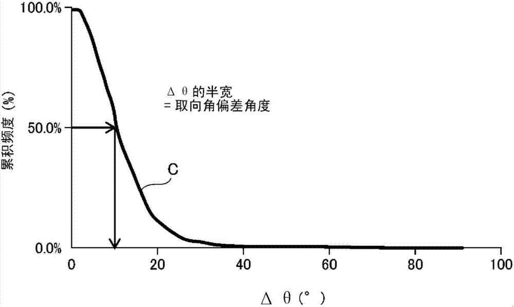
Provided are: a sintered body that forms a rare-earth magnet and is configured in a manner such that the divergence between the orientation angles of the easy axes of magnetization of magnet material particles and the orientation axis angle of the magnet material particles is kept within a prescribed range in an arbitrary micro-section of a magnet cross-section; and a rare-earth sintered magnet. This sintered body for forming a rare-earth magnet has two or more different regions exhibiting an orientation axis angle of at least 20 DEG, given that the orientation axis angle is defined as the highest-frequency orientation angle among the orientation angles of the easy magnetization axes, relative to a pre-set reference line, of a plurality of magnet material particles in a rectangular section at an arbitrary position in a plane including the thickness direction and the widthwise direction. The orientation-angle variance angle is 16.0 DEG or less relative to said orientation axis angle, given that the orientation-angle variance angle is defined on the basis of the difference between the orientation angles of the easy magnetization axes of the magnet material particles. One embodiment defines said section as a rectangular section containing 30 or more magnet material particles, and for example, containing 200 or 300 magnet material particles. It is preferable for the rectangular section to be a square. Another embodiment defines said section as a square section having 35[mu]m sides.

Description

technical field [0001] The present invention relates to a sintered body for forming a rare earth magnet for forming a rare earth sintered magnet, and a rare earth sintered magnet obtained by magnetizing the sintered body. In particular, the present invention relates to a sintered body for forming a rare earth magnet having a structure in which a plurality of magnet material particles containing a rare earth substance and each having an easy axis of magnetization are sintered together, and a sintered rare earth magnet obtained by magnetizing the sintered body. Background technique [0002] Rare-earth sintered magnets have attracted attention as high-performance permanent magnets that can be expected to have high coercive force and residual magnetic flux density, and have been put into practical use, and are being developed for higher performance. Published in, for example, the Journal of the Japan Institute of Metals, Vol. 76, No. 1 (2012), pages 12 to 16 of Une Yasuhiro et a...

Claims


Application Information

Patent Timeline
Patent Type & Authority Applications(China)
IPC IPC(8): H01F7/02H01F1/057H01F1/08B22F1/102
CPCH01F1/0577H01F7/02B22F1/102H01F41/0273C22C38/005C22C38/06C22C38/10C22C38/12C22C38/16H01F1/068B22F2301/355B22F2304/10H01F1/0536
Inventor 藤川宪一山本贵士江部宏史藤原诚井本荣一大牟礼智弘
Owner NITTO DENKO CORP
Learn More