Extrusion forming die for open mold cavity

An extrusion forming and open technology, which is applied in the direction of forming tools, manufacturing tools, metal processing equipment, etc., can solve the problems of increasing repeated heating and drawing processes, easy to produce coarse grains, and long manufacturing process, so as to improve the forming performance and quality, prevent shear deformation, and reduce the effect of the forming process

Active Publication Date: 2017-12-05
NO 59 RES INST OF CHINA ORDNANCE IND
View PDF6 Cites 12 Cited by
  • Summary
  • Abstract
  • Description
  • Claims
  • Application Information

AI Technical Summary

Problems solved by technology

[0002] Thin-wall products with deep blind holes mostly adopt the traditional drawing forming process. The design method of this process mainly depends on the diameter D1 of the inner hole of the final forging, and the design extrusion is carried out according to the principle that the length-to-diameter ratio of the inner hole does not exceed 3, that is, h1≤3×D1. For pressing punching parts, the outer diameter D0 of the extruding punching parts is determined according to the principle of equal volume, and then the blanking size of the bar is determined; this inevitably results in a large wall thickness of the designed extrusion punching parts, and in the long-distance drawing process The middle metal gathers upward quickly. When the drawing deformation is close to the solid bottom area of ​​the inner hole, two large parts of metal with a solid bottom and a thick wall are formed. At this time, the wall thickness of the deformation zone is relatively thinner, and the thinner the wall thickness, the shear The more serious the deformation, it is easy to appear such as image 3 At the same time, the design has to adopt multiple drawing and repeated heating and drawing processes, which is easy to produce coarse grains, long manufacturing process and low efficiency

Method used


Image

  • Extrusion forming die for open mold cavity
  • Extrusion forming die for open mold cavity
  • Extrusion forming die for open mold cavity

Examples


Embodiment Construction

[0025] Embodiments of the present invention will be described below in conjunction with the accompanying drawings.

[0026] (1) The size of the product forging is as follows: Figure 4 , Inner diameter Ф76mm, outer diameter Ф100mm, inner hole length 540mm, total product length 632mm, blank blanking diameter design Ф120mm.

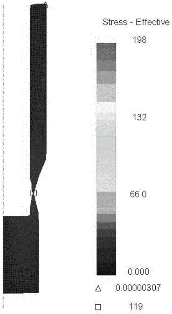
[0027] (2) Firstly, simulate and analyze the extrusion process of the open cavity as follows: Figure 5 , in the extrusion punching stage of the open cavity, when the initial plastic deformation resistance of the material is reached, the stress increases rapidly, which is related to the deformation characteristics of the material; then the open cavity creates good conditions for deformation, which is conducive to eliminating Due to the influence of work hardening, the forming pressure decreases rapidly; with the gradual reduction of the open cavity, the forming load increases significantly, but the overall stress is not large. In the extrusion and drawing...


PUM


Abstract

The invention discloses an extrusion forming die for an open mold cavity. The extrusion forming die mainly comprises an extrusion punching die body and an extrusion pulling die body. In the extrusion punching stage, the open mold cavity is formed by a first female die and a second female die. The second female punching die is of a floating structure and moves downwards along an upper die, the forming load is reduced, and the bend resistance bearing capability of a male die is improved. After a blank makes contact with a first jacking rod, the upper die and an upper ramming cylinder are depressurized; piston rods of a left piston cylinder and a right piston cylinder move upwards to support a female die supporting ring; a left movable supporting block and a right movable supporting block are pulled out horizontally under the effect of a moving and resetting system; a lower die sleeve and the female die supporting ring overall move downwards under the effects of the resilience force of a spring and the pressing force of the upper ramming cylinder in the return stroke process of the left piston cylinder and the right piston cylinder; and when the blank makes complete contact with a lower fixed plate, the open mold cavity is formed again at the moment. The thinning pulling times can be effectively decreased, forming defects such as pull cracks and pull fractures are prevented, and the extrusion forming die for the open mold cavity can be applied to forming of various deep blind hole thin wall products.

Description

technical field [0001] The invention relates to an extrusion mold with an open cavity. Background technique [0002] Thin-wall products with deep blind holes mostly adopt the traditional drawing forming process. The design method of this process mainly depends on the diameter D1 of the inner hole of the final forging, and the design extrusion is carried out according to the principle that the length-to-diameter ratio of the inner hole does not exceed 3, that is, h1≤3×D1. For pressing punching parts, the outer diameter D0 of the extruding punching parts is determined according to the principle of equal volume, and then the blanking size of the bar is determined; this inevitably results in a large wall thickness of the designed extrusion punching parts, and in the long-distance drawing process The middle metal gathers upward quickly. When the drawing deformation is close to the solid bottom area of ​​the inner hole, two large parts of metal with a solid bottom and a thick wall...

Claims


Application Information

Patent Timeline
IPC IPC(8): B21D37/10
CPCB21D37/10
Inventor 黄树海林军赵祖德陈强胡传凯康凤夏祥生舒大禹
Owner NO 59 RES INST OF CHINA ORDNANCE IND
Why Eureka
Try Eureka