Non-mechanical-stirring sludge treatment anaerobic reactor and method for material circulation in reactor

An anaerobic reactor, sludge treatment technology, applied in biological sludge treatment, water/sludge/sewage treatment, chemical instruments and methods, etc. and other problems, to achieve the effect of harmless treatment, alleviation of environmental pressure, and difficult maintenance.

Pending Publication Date: 2017-12-05
青岛中环能生物科技有限公司
View PDF1 Cites 3 Cited by
  • Summary
  • Abstract
  • Description
  • Claims
  • Application Information

AI Technical Summary

Problems solved by technology

However, the above technologies cannot take into account the biogas raw material circulation, raw material adaptability, biogas output rate and energy consumption at the same time. There are still insufficient biogas reaction raw material circulation and stirring, single raw material, small volume, high failure rate, and difficult maintenance. , one or more disadvantages of low biogas volumetric yield and high energy consumption
Due to the limitation of material characteristics, many high-efficiency anaerobic reactors in China are difficult to be effectively applied and cannot achieve good results. Traditional anaerobic reactors have not really met the requirements of biogas industrial production.
However, there are few studies on sludge anaerobic reactor at home and abroad, and the research on sludge anaerobic fermentation to biogas needs to be solved urgently.

Method used


Image

  • Non-mechanical-stirring sludge treatment anaerobic reactor and method for material circulation in reactor

Examples


Embodiment 1

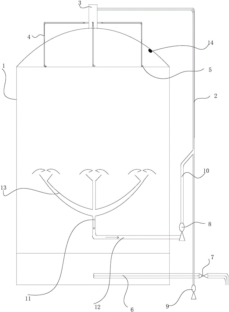
[0026] refer to figure 1 , the anaerobic reactor of the present invention includes a fermenter tank body 1, an inlet and outlet system, and a material circulation system; wherein, the inlet and outlet system includes a main feed pipe 2, a discharge pipe 6 connected to the bottom of the tank body 1, and a second A feeding pump 8, the first feeding pump 8 is used to pump external materials into the tank body 1 through the main feeding pipe 2; the top wall of the tank body 1 is provided with a feeding port, and the outlet of the main feeding pipe 2 The material end is connected with the feed port, so that the external material enters the tank body from the feed port at the top of the tank body 1; the material circulation system includes a material absorption main pipe arranged in the middle and lower part of the tank body 1, and a main The auxiliary feed pipe 10 connected by the feed pipe 2; the discharge end of the material absorption main pipe communicates with the auxiliary fe...

Embodiment 2

[0038] In addition, the present invention also proposes a method based on the material circulation in the above-mentioned anaerobic reactor, which can improve the circulation of the reaction material in the anaerobic reactor to ensure that the material is fully fermented, and can make full use of the organic waste generated by urban life, Especially domestic sludge.

[0039] It is achieved through the following steps:

[0040] Pump the pretreated reaction material from the top of the anaerobic reactor tank through the main feed pipe outside the anaerobic reactor, and when it reaches the specified height, stop feeding and start slag discharge. At this time, the second feed pump starts The material in the tank is continuously circulated at a certain flow rate;

[0041] When the liquid level in the reaction tank drops to a certain height, the slag discharge is stopped, and at the same time, the main feeding pipe and the auxiliary feeding pipe are fed to the designated height in ...

Embodiment 3

[0043] The method based on material circulation in the above-mentioned anaerobic reactor of the present embodiment, it comprises the steps:

[0044] First, pump the pretreated sludge into the anaerobic reactor tank from the top of the reactor tank through the main feed pipe. When the liquid level of the pumped material is 1.4 meters away from the tank top, the controller controls the feed valve and The first feed pump is turned off to stop feeding, and the discharge valve is controlled to open to discharge the discharge pipe and slag. At the same time, the second feed pump is controlled to open, and the second feed pump starts to circulate the material in the tank at a certain flow rate without interruption. ;

[0045] When the height of the liquid level in the tank detected by the liquid level detector is greater than or equal to 1.6 meters from the tank top, the controller controls the discharge valve to close to stop slag discharge, and at the same time controls the feed va...


PUM


Abstract

The invention brings forward a non-mechanical-stirring sludge treatment anaerobic reactor, which comprises a fermentation tank body and a feeding and discharging system. The feeding and discharging system comprises a main feed pipe and a discharge pipe which is communicated with the bottom of the tank body. The top of the tank body is provided with a feed inlet. A discharge end of the main feed pipe is communicated with the feed inlet. The feeding and discharging system also comprises a first feeding pump, which is used for pumping external materials into the tank body through the main feed pipe. A material circulation system comprises a material absorption header-pipe arranged at the lower middle part inside the tank body, and an auxiliary feed pipe which is arranged outside the tank body and is communicated with the main feed pipe. A discharge end of the material absorption header-pipe is communicated with the auxiliary feed pipe through a second feeding pump. The domestic sludge treatment technology is based on the non-mechanical-stirring anaerobic reactor. According to the technology, the anaerobic reactor adopts the mode of feeding at upper part and circulating at middle part to form an internal circulating fluid system of the material. Thus, problems such as nonuniform distribution, crusting at top of the tank, etc. are solved. The invention also brings forward a method for material circulation in the anaerobic reactor. According to the invention, anaerobic fermentation treatment of domestic sludge is mainly solved.

Description

technical field [0001] The invention belongs to the technical field of sludge treatment, and in particular relates to a non-mechanical stirring sludge treatment method for anaerobic reactor and material circulation in the reactor, and anaerobic fermentation treatment for domestic sludge. Background technique [0002] During the development of biogas industrialization, a variety of anaerobic reactor technologies have been popularized and used, such as: setting mechanical stirring devices in anaerobic reaction tanks, horizontal anaerobic reactors, downflow anaerobic filters and upflow anaerobic reactors. Anaerobic reaction tanks, adding circulation pipes in anaerobic reactors, etc. However, the above technologies cannot take into account the biogas raw material circulation, raw material adaptability, biogas output rate and energy consumption at the same time. There are still insufficient biogas reaction raw material circulation and stirring, single raw material, small volume, ...

Claims


Application Information

Patent Timeline
Patent Type & Authority Applications(China)
IPC IPC(8): C02F11/04
CPCC02F11/04C02F2301/04C02F2209/42
Inventor 蒋勇郭清吉孙梦圆
Owner 青岛中环能生物科技有限公司
Why Eureka
Try Eureka