RFID label and preparation method
An RFID tag and antenna technology, applied in the field of RFID electronic tags, to achieve the effect of mature and simple process
- Summary
- Abstract
- Description
- Claims
- Application Information
AI Technical Summary
Problems solved by technology
Method used
Image

Examples
Embodiment 1
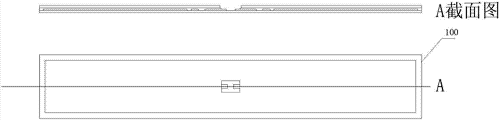
[0146] see Figure 16 , the water-washable RFID tag provided by this example is mainly composed of antenna 100 (such as figure 1 shown), chip 101, cofferdam metal ring 102a, buffer sheet 103, reinforcing plate 104, and thermosetting adhesive 105 are processed and combined. Its specific preparation process is as follows (as Figure 17 shown):
[0147] In step P111, the buffer sheet 103 and the reinforcement 104 are successively pasted on the opposite side of the chip mounting position on the finished antenna 100; when the buffer sheet 103 is pasted, the notches on it correspond to the signal lines of the antenna; on the PI buffer sheet After the 103 is aligned and mounted, it is pressed by high temperature and high pressure.
[0148] Step P112 , soldering the chip 101 and the cofferdam metal ring 102a to the corresponding positions of the antenna 100 by SMT process.
[0149] In step P113, after the soldering is completed, the chip is strengthened and protected by dispensing...
Embodiment 2
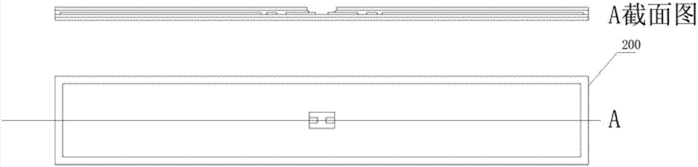
[0152] see Figure 18 , The RFID tag provided in this example is mainly composed of an antenna 200, a chip 101, a cofferdam metal ring 102a, a buffer sheet 103, a reinforcing plate 104, and a thermosetting adhesive 105.
[0153] The concrete preparation process of this RFID label is as follows (as Figure 19 shown):
[0154] Step P211, in the finished antenna 200 (such as figure 2 As shown) the reverse side of the upper chip mounting position is pasted with buffer sheet 103 and reinforcement 104 successively; when bonding buffer sheet 103, make the notch on it correspond to the signal line of the antenna; after PI buffer sheet 103 is aligned and mounted , and then pressed under high temperature and high pressure.
[0155] Step P212, welding the chip 101 and the cofferdam metal ring 102a to the corresponding position of the antenna 200 through the SMT process;
[0156] In step P213, after the welding is completed, the chip is strengthened and protected by dispensing and cu...
Embodiment 3
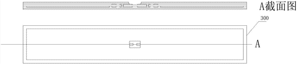
[0159] see Figure 20 , the RFID tag provided in this example is mainly composed of antenna 300, chip 101, cofferdam metal ring 102a, buffer sheet 103, reinforcing plate 104, and thermosetting adhesive 105.
[0160] The concrete preparation process of this RFID label is as follows (as Figure 21 shown):
[0161] Step P311, in the finished antenna 300 (such as image 3 As shown) the reverse side of the upper chip mounting position is pasted with buffer sheet 103 and reinforcement 104 successively; when bonding buffer sheet 103, make the notch on it correspond to the signal line of the antenna; after PI buffer sheet 103 is aligned and mounted , and then pressed under high temperature and high pressure.
[0162] In step P312, solder the chip 101 and the metal ring 102a of the cofferdam to the corresponding position of the antenna 300 by SMT process.
[0163] In step P313, after the soldering is completed, the chip is strengthened and protected by dispensing and curing the hea...
PUM
 Abstract
Description
Claims
Application Information
 - R&D
- Intellectual Property
- Life Sciences
- Materials
- Tech Scout
- Unparalleled Data Quality
- Higher Quality Content
- 60% Fewer Hallucinations
Browse by: Latest US Patents, China's latest patents, Technical Efficacy Thesaurus, Application Domain, Technology Topic, Popular Technical Reports.
© 2025 PatSnap. All rights reserved.Legal|Privacy policy|Modern Slavery Act Transparency Statement|Sitemap|About US| Contact US: help@patsnap.com