Microstrip broadband dual-frequency combiner

A frequency combiner and broadband technology, applied in the field of micro-bandwidth dual-frequency combiners, can solve the problems of poor controllability, high cost, complex structure of the combiner, etc.

Inactive Publication Date: 2017-12-08
DEQING LIWEI COMM TECH CO LTD
View PDF2 Cites 0 Cited by
  • Summary
  • Abstract
  • Description
  • Claims
  • Application Information

AI Technical Summary

Problems solved by technology

[0003] The traditional combiner is generally composed of two coaxial cavity bandpass filters. The relative bandwidth of this combiner is only 20% or even lower. , making the structure of the combiner realized in this way complex, difficult to assemble and debug, large in size and high in cost, and poor in controllability

Method used


Image

  • Microstrip broadband dual-frequency combiner

Examples


Embodiment Construction

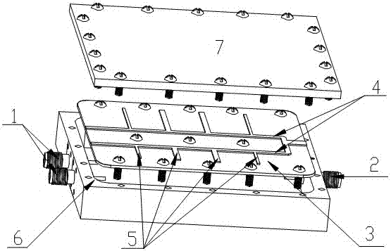
[0008] like figure 1 As shown, the micro-broadband dual-frequency combiner of the present invention includes two radio frequency input ports 1 connected to the outside, a radio frequency output port 2, a dielectric substrate 3, a microstrip transmission line 4, a 1 / 4 wavelength branch open line 5, Combiner metal shell 6, metal cover plate 7, the microstrip transmission line 4 and 1 / 4 wavelength branch open line are distributed on the dielectric substrate 3, the entire dielectric substrate is fixed on the cavity with screws, and then the metal cover The sealed cavity of the board 7 forms a complete broadband microstrip dual-frequency combiner.

[0009] Multiple sections of 1 / 4 wavelength branch opening lines 5 are distributed on the microstrip transmission line 4 to form two band rejection filters. By adjusting the number, wavelength, line width and 1 / 4 wavelength branch opening lines 5 of the 1 / 4 wavelength branch The distance between the opening lines 5 can adjust the pass-b...


PUM


Abstract

The invention provides a microstrip broadband dual-frequency combiner. The microstrip broadband dual-frequency combiner consists of two radio frequency input ports connected with the external, a radio frequency output port, a dielectric substrate, a microstrip transmission line, a 1 / 4 wavelength branch open-circuit line, a combiner metal shell and a metal cover plate to form two band elimination filters left and right; the broadband signals input from the two radio frequency input ports are filtered through the two band elimination filters; and a stop band is selected to form high out-of-band suppression on another broadband signal within another broadband signal range. The invention provides the microstrip broadband dual-frequency combiner with simple structure and low cost.

Description

technical field [0001] The invention relates to a broadband combining method in a dual-frequency combiner system, in particular to a micro-broadband dual-frequency combiner. Background technique [0002] At present, the development of communication technology is changing with each passing day. In order to realize resource sharing, reduce the volume and weight of modules, and reduce system costs, the application of multiple frequency bands sharing antenna feeder systems is becoming more and more common. Therefore, multi-band combining and splitting technology has become An important direction for the development of communication technology. [0003] The traditional combiner is generally composed of two coaxial cavity bandpass filters. The relative bandwidth of this combiner is only 20% or even lower. , making the structure of the combiner implemented in this way complex, difficult to assemble and debug, large in size and high in cost, and poor in controllability. The presen...

Claims


Application Information

Patent Timeline
Patent Type & Authority Applications(China)
IPC IPC(8): H01P1/213
CPCH01P1/2135
Inventor 邓庆杰
Owner DEQING LIWEI COMM TECH CO LTD
Why Eureka
Try Eureka