A high-speed asynchronous motor electric spindle internal and external cooling structure and temperature cooperative control system

An asynchronous motor, collaborative control technology, applied in the direction of manufacturing tools, metal processing machinery parts, metal processing equipment, etc., can solve the problem of long-term heat dissipation of the electric spindle, stability and reliability problems, heat pipe structure and size and can not effectively solve the problem. The problem of limited heat exchange power, etc., can achieve the effect of shortening the thermal equilibrium time of the system, changing the working conditions, and reducing the axial thermal deformation.

Active Publication Date: 2019-10-11
XI AN JIAOTONG UNIV
View PDF6 Cites 0 Cited by
  • Summary
  • Abstract
  • Description
  • Claims
  • Application Information

AI Technical Summary

Problems solved by technology

Although it has a cooling effect on the shaft core of the electric spindle to a certain extent, due to the structural size of the heat pipe itself and the limited heat exchange power, this cooling scheme cannot effectively solve the heat dissipation problem caused by the long-term and high-power processing of the electric spindle.
In addition, there are problems with the stability and reliability of its operation

Method used


Image

  • A high-speed asynchronous motor electric spindle internal and external cooling structure and temperature cooperative control system
  • A high-speed asynchronous motor electric spindle internal and external cooling structure and temperature cooperative control system
  • A high-speed asynchronous motor electric spindle internal and external cooling structure and temperature cooperative control system

Examples


Embodiment Construction

[0031] Below in conjunction with accompanying drawing, the present invention is described in further detail:

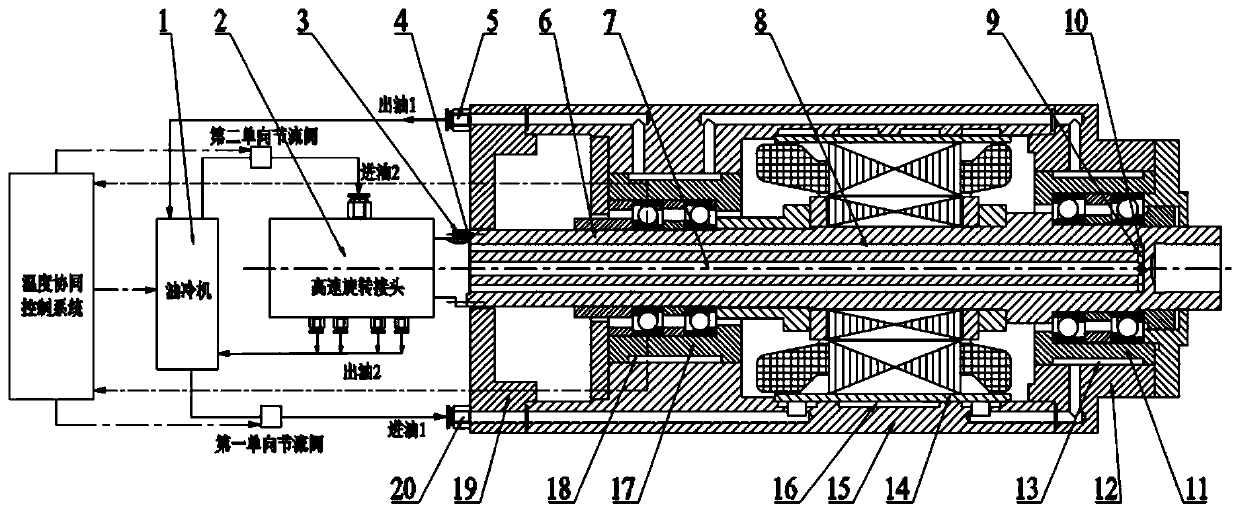
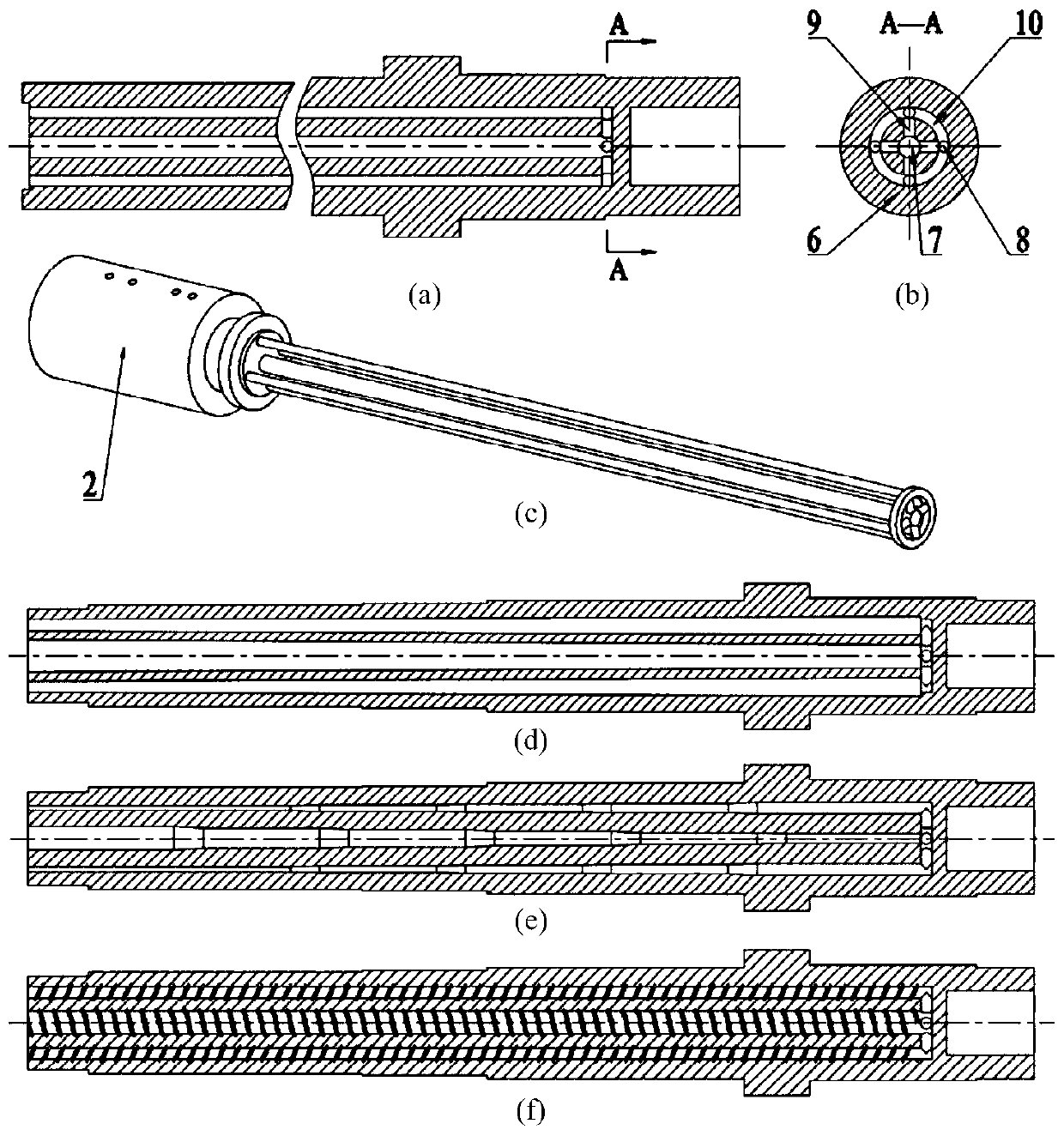
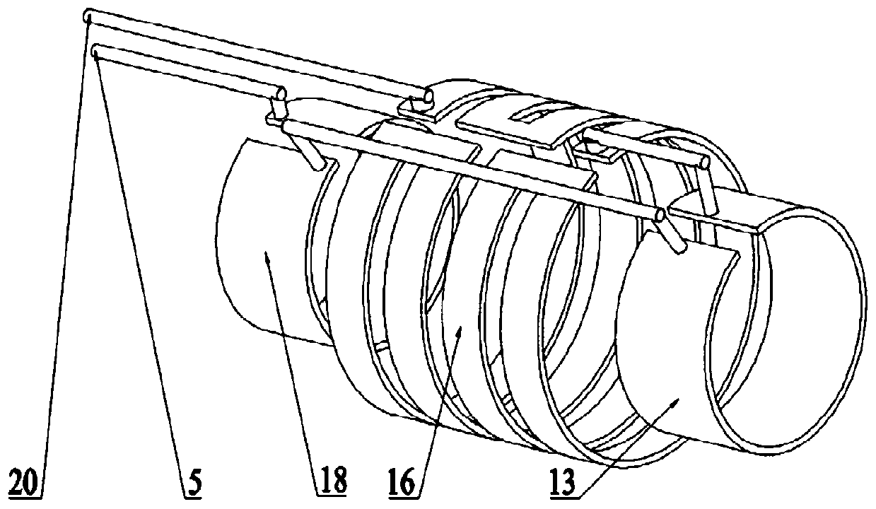
[0032] Reference attached Figure 1 to Figure 5 , an internal and external cooling structure and temperature coordinated control system of a high-speed asynchronous motor electric spindle. The inner and front bearing housings 11 and the rear bearing housings 17 respectively surround the motor stator and the front and rear bearings to process external annular cooling flow passages connected in series, and the flow passages pass through the stator cooling jacket 16, the front bearing cooling jacket 13, and the rear bearing cooling jacket in turn. 18. Both the electric spindle external cooling inlet 20 and the external cooling outlet 5 are arranged on the rear end cover 19 of the electric spindle. The internal cooling inflow channel 7 of the electric spindle is located on the center line of the electric spindle core 6 , and the internal cooling return channel 8 of the e...


PUM


Abstract

The invention discloses a high-speed asynchronous motor electric spindle internal and external cooling structure and temperature cooperative control system. A mouse cage type cooling flow channel is machined in an electric spindle core, and a high-speed rotating joint is connected with the back end face of the electric spindle core in a fastening manner in order to achieve input and output of a cooling medium in the cooling channel; meanwhile, an annular cooling flow channel is machined around a motor stator in an electric spindle shell, an annular cooling flow channel is machined around a front bearing in a front bearing pedestal, an annular cooling flow channel is machined around a back bearing in a back bearing pedestal, and the annular cooling flow channels are connected in series and communicate with the outside through the shell. A forced circulation cooling system is formed by the internal and external cooling structure, the temperature and the flow of cooling liquid in the internal and external channels are adjusted by the temperature cooperative control system according to temperature feedback of key points, and circular and efficient cooling of an electric spindle system is achieved under the variable working condition. According to the high-speed asynchronous motor electric spindle internal and external cooling structure and temperature cooperative control system, direct and efficient cooperative forced circulation cooling on high-speed asynchronous motor electric spindle main heating parts such as the motor stator, a motor rotor, the front bearing and the back bearing can be achieved, thermal deformation of an electric spindle is reduced, and the thermal stability of the electric spindle is improved.

Description

technical field [0001] The invention relates to the technical field of electric spindle cooling, in particular to an internal and external cooling structure and temperature coordinated control system of an electric spindle of a high-speed asynchronous motor. Background technique [0002] A large number of research and production practices have shown that in modern mechanical manufacturing errors, the error caused by thermal deformation reaches 50%, and in high-speed and high-precision machining, the proportion is as high as 60% to 80%. As a key component of high-speed and high-precision CNC machine tools, the electric spindle's performance directly affects the machining accuracy of the machine tool. Because the electric spindle motor is built-in and the shell is closed, the heat generated by the power loss of the motor and the heat generated by the friction of the front and rear bearings cannot be exported in a timely and effective manner, and a large amount of heat is accum...

Claims


Application Information

Patent Timeline
Patent Type & Authority Patents(China)
IPC IPC(8): B23Q11/12
Inventor 史晓军朱科高建民李法敬王维库
Owner XI AN JIAOTONG UNIV
Why Eureka
Try Eureka