Decoupling drive-by-wire brake system and control method thereof

A brake-by-wire and decoupling technology, applied in the direction of brakes, brake transmission devices, automatic starting devices, etc., can solve the problems of high design standards and defective configuration scheme safety, and achieve lower response requirements and lower power requirements. Effect

Pending Publication Date: 2017-12-12
WUHU BETHEL ELECTRONICS CONTROL SYST
View PDF10 Cites 17 Cited by
  • Summary
  • Abstract
  • Description
  • Claims
  • Application Information

AI Technical Summary

Problems solved by technology

In short, the configuration scheme requires high design standards, and the security of the configuration scheme is flawed

Method used


Image

  • Decoupling drive-by-wire brake system and control method thereof
  • Decoupling drive-by-wire brake system and control method thereof
  • Decoupling drive-by-wire brake system and control method thereof

Examples


Embodiment Construction

[0060] The specific implementation of the present invention will be described in further detail below by describing the embodiments with reference to the accompanying drawings, so as to help those skilled in the art have a more complete, accurate and in-depth understanding of the inventive concepts and technical solutions of the present invention.

[0061] One, overall structure of the present invention:

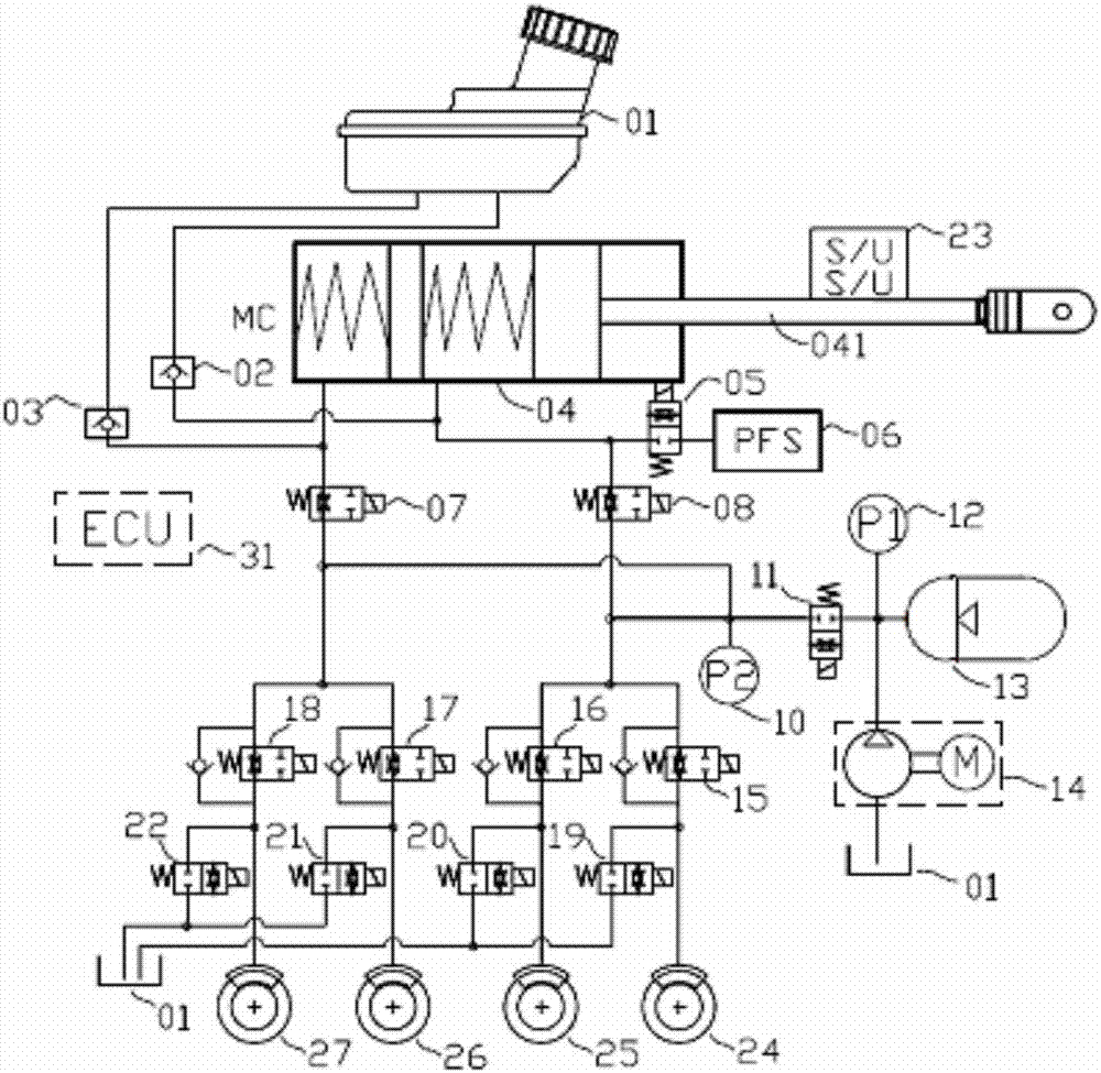
[0062] 1, figure 1 It is a structural schematic diagram of the wire-controlled hydraulic brake system of the present invention.

[0063] Two one-way valves 02 and 03 are connected between the brake master cylinder 04 and the oil pot 01, and the conduction direction of the one-way valves is from the oil pot to the brake master cylinder; the master cylinder stroke sensor 23 It is not limited to use single-channel and multi-channel linear sensors, linear displacement sensors, or angular displacement sensors.

[0064] The pedal feeling simulator PFS06 is connected to one of t...


PUM


Abstract

The invention discloses a decoupling drive-by-wire brake system. The decoupling drive-by-wire brake system comprises an oil pot (01), oil pot liquid outlet check valves (02 and 03), a brake master cylinder (04), a pedal feeling simulator (PFS) (06), block valves (07 and 08), a linear normally closed valve (11), a high-pressure accumulator pressure sensor (12), a high-pressure accumulator (13), a motor-pump pressurization system (14), pipeline pressure increasing valves (15, 16, 17 and 18), pipeline pressure reducing valve (19, 20, 21 and 22), a pedal stroke sensor (23) and an ECU (31). According to the decoupling drive-by-wire brake system, compared with a configuration scheme that an auxiliary main cylinder is driven by a motor, the response requirement for the motor-pump system is reduced, the power requirement of the motor and the ECU is reduced, and the safety performance of the system is improved.

Description

technical field [0001] The invention belongs to the technical field of automobile brake systems. More specifically, the present invention relates to a decoupled brake-by-wire system. In addition, the present invention also relates to a control method of the above braking system. Background technique [0002] The boost of the traditional automobile braking system is to use the vacuum generated by the engine or the vacuum generated by the electronic vacuum pump to realize the brake pressure build-up in the vacuum booster. Such as Figure 17 Shown is a traditional automobile braking system, including a vacuum booster 4 . When the driver brakes, the brake pedal 6 is stepped on, and the brake master cylinder 3 is driven to pass through the electronically controlled pressure regulating unit ABS / ESC2 to build up pressure on the brake 1 to generate brake fluid pressure; a vacuum booster is needed for the pedal during this process. The force is proportionally amplified, so that th...

Claims


Application Information

Patent Timeline
Patent Type & Authority Applications(China)
IPC IPC(8): B60T13/74B60T13/68B60T7/12
CPCB60T7/12B60T13/68B60T13/745
Inventor 袁永彬徐文泉张平平黄先明
Owner WUHU BETHEL ELECTRONICS CONTROL SYST
Why Eureka
Try Eureka