
Submerged bridge pile foundation scouring real-time monitoring system and monitoring method thereof

A real-time monitoring system and submerged technology, applied in the field of measurement, can solve the problems of inability to monitor changes in earth pressure, interference of measurement accuracy, and different applicable conditions, and achieve real-time monitoring of engineering layout, easy engineering layout, and high durability. Effect

Active Publication Date: 2017-12-12
ZHEJIANG UNIV OF TECH
View PDF5 Cites 16 Cited by
  • Summary
  • Abstract
  • Description
  • Claims
  • Application Information

AI Technical Summary

Problems solved by technology

However, these methods have different monitoring accuracy and different applicable conditions: First, these methods generally cannot be continuously tested in real time, and need to be observed regularly, and cannot eliminate the influence of complex reciprocating changes in the erosion and sediment layer. Only the depth change of the water-sediment interface does not take into account the density change of the sediment layer below the interface, so it is impossible to accurately determine whether the lateral soil pressure of the pile foundation has changed
Its measurement accuracy is also very susceptible to interference from external environments such as waves, and it needs to be constantly corrected to adapt to environmental changes in different waters, and the operation is complicated.
Second, this method cannot monitor the changes in earth pressure caused by the scour near the bridge pile foundation, and what is obtained is the evolution of large-scale underwater terrain scour, and the pile side is the blind spot of the test instead.

Method used


Image

  • Submerged bridge pile foundation scouring real-time monitoring system and monitoring method thereof
  • Submerged bridge pile foundation scouring real-time monitoring system and monitoring method thereof
  • Submerged bridge pile foundation scouring real-time monitoring system and monitoring method thereof

Examples


Embodiment Construction

[0031] The present invention will be further described below in conjunction with the accompanying drawings of the description.

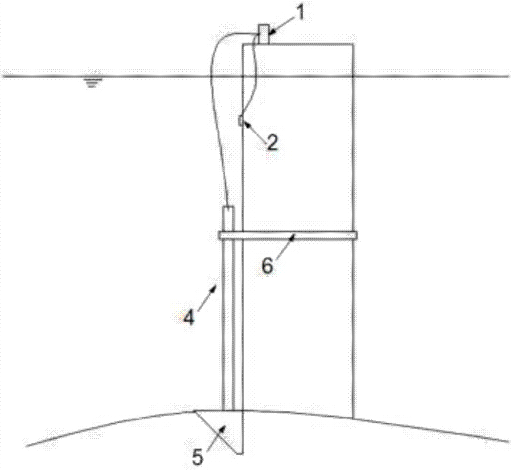
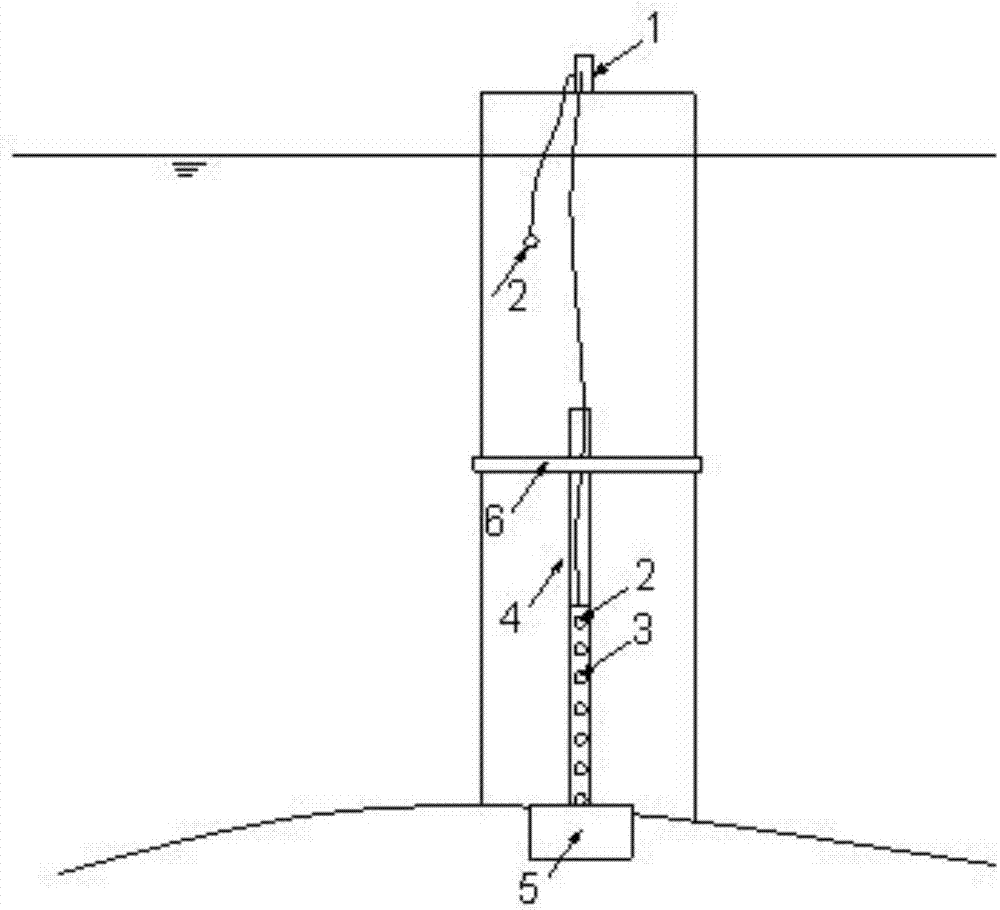
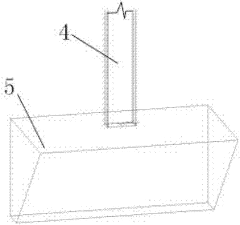
[0032] like Figure 1-8 As shown, a submerged bridge pile foundation scour real-time monitoring system and monitoring method thereof, including a data processing system 1, a fiber grating micro seepage pressure sensor 2, a fiber grating pressure sensor 3, a monitoring guide beam 4, a sinker 5 and a limiter bit device6.

[0033] The data processing system 1 is set on the top of the bridge pier at the monitoring point. The data processing system 1 is a wireless transmission fiber grating demodulator, connected to the sensor through an optical fiber data line, and transmits the data from the sensor to the cloud database through wireless transmission. The real-time status of pier scour can be obtained through data comparison and analysis by computer.

[0034] There are two fiber grating miniature osmotic pressure sensors 2, one is set on the outer wall...


PUM


Abstract

The invention discloses a submerged bridge pile foundation scouring real-time monitoring system and a monitoring method thereof. A data processing system is arranged at the top of a pier. A fiber bragg grating seepage pressure microsensor is arranged on the surface of the outer wall, located under the water, of the pier. A sunk block is arranged at the position, close to the pile foundation, of a river bed at the bottom of the pile foundation. A monitoring guide beam is fixedly arranged on the sunk block. A limiting device used for preventing the monitoring guide beam from moving in the radial direction is arranged in the middle of the pier. A fiber bragg grating seepage pressure microsensor and a set of fiber bragg grating pressure sensors are arranged at the lower end of the monitoring guide beam. The submerged bridge pile foundation scouring real-time monitoring system and the monitoring method thereof have the beneficial effects that the monitoring system and method are suitable for monitoring pile side pressure changes caused by scouring and water pressure changes caused by water level fluctuation near the underground pile foundation in real time, thus, the influences of pile side flow scouring and water level on pile foundation safety are obtained through analyzing, and the monitoring system and method have the advantages of high durability and precision, simple structure, real-time monitoring and easy engineering layout.

Description

technical field [0001] The invention relates to the technical field of measurement, in particular to a real-time monitoring system and a monitoring method for scour of submerged bridge pile foundations. Background technique [0002] Bridges are an important part of highway and railway traffic. Its maintenance status directly affects the smooth flow of roads and driving safety. my country is a big country of bridges. Many bridges are located on rivers, lakes and seas. The pile foundations of bridges inevitably receive water flow. The continuous scouring of the water flow is the main factor causing the instability of the bridge piers. [0003] Underwater pile foundations of cross-sea and river-crossing bridges will be affected by water erosion, and soil erosion and silting changes on the pile side will occur, which will affect the soil pressure on the pile side and the safety of the pile foundation. Therefore, in recent years, how to observe the underwater foundation soil near...

Claims


Application Information

Patent Timeline
IPC IPC(8): E02D33/00
CPCE02D33/00E02D2600/10
Inventor 赵钦郭健吴继熠
Owner ZHEJIANG UNIV OF TECH
Learn More