High-temperature and high-pressure special adjusting valve

A high temperature and high pressure, regulating valve technology, applied in the direction of lift valve, valve details, valve device, etc., can solve the problems of low operating temperature, affecting performance, poor sealing effect, etc., to achieve high anti-cavitation and noise reduction performance, easy to use. Maintenance and replacement, good positioning and guiding effect

Pending Publication Date: 2017-12-12
上海范雨实业有限公司
View PDF0 Cites 2 Cited by
  • Summary
  • Abstract
  • Description
  • Claims
  • Application Information

AI Technical Summary

Problems solved by technology

[0004] 2. The inner wall of the valve core (04) is too thin. When it encounters high temperature, the principle of thermal expansion is easy to deform at high temperature, and it is easy to leak with the metal seal of the bottom valve seat, and it is easy to lock with the sleeve (05), which affects the performance;
[0006] 4. After the valve stem (07) and the valve core (04) are connected to the thread, they are welded, which cannot be replaced online, and the maintenance of the equipment is troublesome;
[0007] 5. The packing group (08) is short in combination, the relative distance of the seal is relatively shortened, and it is far away from the valve core, so it cannot guide the valve core;
[0009] In short, as far as the conventional regulating valve at room temperature is concerned, due to insufficient standardization and modularization, its operating temperature is low and the pressure difference is low; The problems of low differential and high friction, and its environmental applicability, low reliability, and durability

Method used


Image

  • High-temperature and high-pressure special adjusting valve
  • High-temperature and high-pressure special adjusting valve
  • High-temperature and high-pressure special adjusting valve

Examples


Embodiment Construction

[0034] In order to make the object, technical solution and advantages of the present invention clearer, the present invention will be further described in detail below in combination with specific examples and with reference to the accompanying drawings. It should be understood that these descriptions are exemplary only, and are not intended to limit the scope of the present invention. Also, in the following description, descriptions of well-known structures and techniques are omitted to avoid unnecessarily obscuring the concept of the present invention.

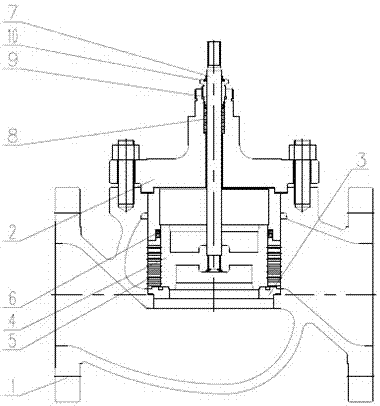
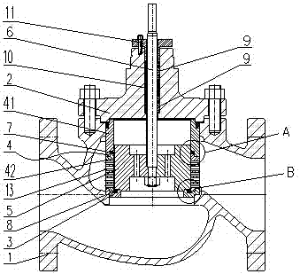
[0035] In industrial automation control, it is often necessary to use a regulating valve to control flow, temperature and pressure; the poppet valve of the present invention has the sealing performance, high pressure bearing and adjustable flow ratio under high temperature environment; The principle is that one valve bottom is sealed by the combination of valve plug and valve seat slope plus metal spring energy storage seali...


PUM


Abstract

The invention discloses a high temperature and high pressure special regulating valve, which comprises a valve body, a valve cover, a valve seat, a valve cage, a valve plug and a valve stem. A built-in space, a valve seat is provided at the lower part of the built-in space; a valve cage is provided between the valve seat and the bonnet, and the valve cage includes an upper valve cage and a lower valve cage arranged from top to bottom, the upper valve cage and the lower valve cage There is an upper seal between them; there is a valve plug inside the cage, the valve plug is set above the valve seat, and a lower seal is provided between the valve plug and the valve seat; there is a valve stem inside the valve plug, the valve plug and The valve stems are connected by pre-positioning and anti-loosening threads. The upper part of the valve stem is installed in the center of the bonnet. There is a graphite packing between the valve stem and the bonnet. The high-temperature and high-pressure special regulating valve of the present invention can effectively improve the sealing performance of the valve at high temperature, withstand high pressure, reliability and versatility; it can be widely used in various automatic high-temperature and high-pressure regulating occasions.

Description

technical field [0001] The invention relates to the technical field of automatic control, in particular to a high-temperature and high-pressure special regulating valve capable of controlling flow, temperature and pressure, with good sealing performance, high reliability and durability. Background technique [0002] In industrial automation control, regulating valves are often used to control flow, temperature and pressure. Existing regulating valve, its structure is as attached figure 1 As shown, it includes valve body (01), valve cover (02), valve seat (03), valve core (04), sleeve (05), balance seal ring (06), valve stem (07), packing group (08), gland (09), dustproof ring (010). Such structures have the following disadvantages: [0003] 1. The valve seat (03) and the valve core are sealed in two places, one is a metal seal and the other is a soft seal. Since the soft seal is made of plastic products, its elasticity is poor and it cannot withstand high temperatures. Th...

Claims


Application Information

Patent Timeline
Patent Type & Authority Applications(China)
IPC IPC(8): F16K1/36F16K1/32F16K41/02F16K27/02F16K47/02F16K27/12
CPCF16K1/36F16K1/32F16K27/02F16K27/12F16K41/02F16K47/02
Inventor 王永茂王永正刘方宗刘韩艳刘成冰王奎
Owner 上海范雨实业有限公司
Why Eureka
Try Eureka