
Smelting furnace for producing copper products

A technology for copper products and furnaces, which is applied in the field of furnaces for the production of copper products, can solve problems such as improper operation, danger, chilling, etc., and achieve the effect of simple structure and avoiding crucible rupture

Active Publication Date: 2017-12-12
铜陵聚福缘铜艺有限公司
View PDF6 Cites 1 Cited by
  • Summary
  • Abstract
  • Description
  • Claims
  • Application Information

AI Technical Summary

Problems solved by technology

[0002] The induction melting furnace has the advantages of small size, light weight, high efficiency, low power consumption, low temperature around the furnace, less smoke and dust, good working environment, simple operation process, reliable smelting operation, fast melting temperature rise, easy control of furnace temperature and high production efficiency. , a variety of advantages such as high furnace utilization rate are widely used in the melting of small and medium-sized copper products, because some liquid copper will be left in the crucible during melting to promote the melting of copper materials, but large pieces of copper are directly added to a small amount of metal liquid In the middle, it will cause chilling or metal solidification, which will cause the crucible to burst immediately, so it is necessary to ensure that the copper parts must be dried and preheated before being added, and the small pieces must be added to the bottom of the crucible first to pave the way for the large ingots and avoid large pieces. Throwing it directly into the crucible will cause it to break. These processes require workers to work at close range and at the same time increase the intensity of work, often resulting in improper operation and causing danger.

Method used


Image

  • Smelting furnace for producing copper products
  • Smelting furnace for producing copper products
  • Smelting furnace for producing copper products

Examples


Embodiment Construction

[0014] In order to further understand the content of the present invention, the present invention will be described in detail in conjunction with the accompanying drawings and embodiments. It should be understood that the examples are only for explaining the present invention and not for limiting it.

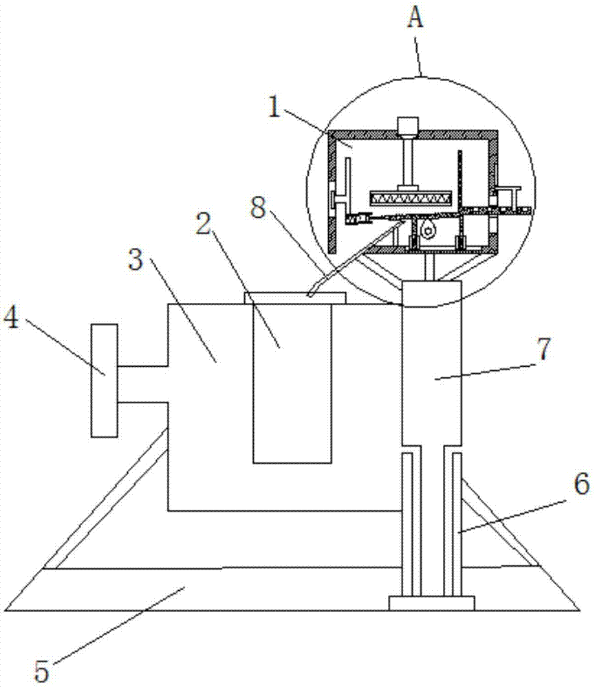
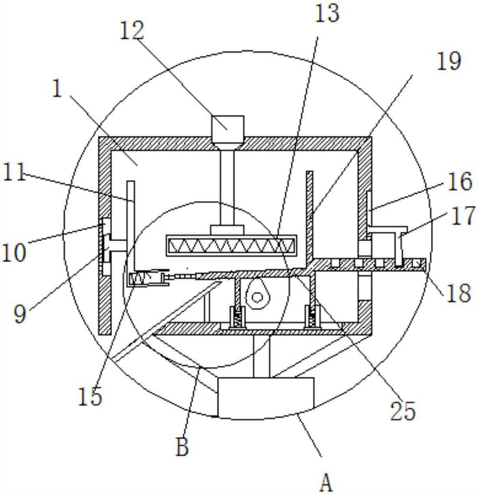
[0015] A melting furnace for the production of copper products includes a feeding box 1, a crucible 2 and a furnace body 3, a furnace body 3 is provided below the feeding box 1, and a feeding port is opened above the feeding box 1 for feeding materials. The inside of the body 3 is fixedly connected with the crucible 2, the outside of the furnace body 3 is fixedly connected with the tilting rod 4, the furnace body 3 is fixedly connected on the base 5, and one end of the base 5 is fixedly connected with the first sleeve 6, and the first sleeve A support frame 7 is movably inserted in the 6, and the top of the support frame 7 is fixedly connected with a feeding box 1;

[0016] The...


PUM


Abstract

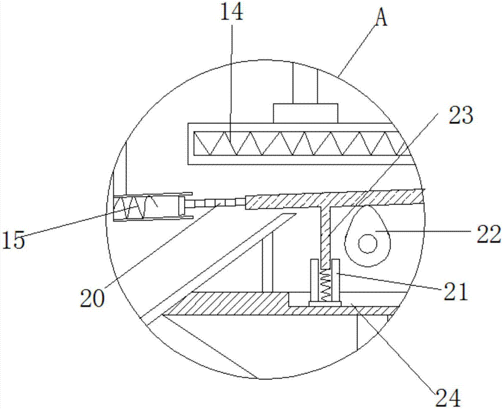
The invention discloses a smelting furnace for producing copper products. The smelting furnace comprises a feeding box, a crucible and a furnace body. The furnace body is arranged below the feeding box. The crucible is fixedly connected into the furnace body. The outer side of the furnace body is fixedly connected with a furnace tilting rod. The furnace body is fixedly connected to a base. One end of the base is fixedly connected with a first sleeve, and a supporting frame is movably inserted into the first sleeve. The top end of the supporting frame is fixedly connected with the feeding box. The high-temperature smelting furnace for producing the copper products is simple in structure, the phenomenon that workers make close contact with the high-temperature smelting furnace is avoided by adding the combination of an electric resistance wire, a leaking net and a cam, uniform feeding is achieved, heating is conducted while stirring is performed, block-shaped materials which are added can be fully preheated rapidly, crushed materials can sink to the bottom through rotation of the cam and further leak out of the leaking net to enter the crucible, automatic screening in the feeding process is realized, and the crucible crushing danger caused by improper manual operation is avoided.

Description

technical field [0001] The invention relates to the technical field of metal processing, in particular to a furnace for producing copper products. Background technique [0002] The induction melting furnace has the advantages of small size, light weight, high efficiency, low power consumption, low temperature around the furnace, less smoke and dust, good working environment, simple operation process, reliable smelting operation, fast melting temperature rise, easy control of furnace temperature and high production efficiency. , a variety of advantages such as high furnace utilization rate are widely used in the melting of small and medium-sized copper products, because some liquid copper will be left in the crucible during melting to promote the melting of copper materials, but large pieces of copper are directly added to a small amount of metal liquid In the middle, it will cause chilling or metal solidification, which will cause the crucible to burst immediately, so it is ...

Claims


Application Information

Patent Timeline
Patent Type & Authority Applications(China)
IPC IPC(8): F27B14/08F27D3/00F27D13/00
CPCF27B14/0806F27B2014/085F27D3/0031F27D13/00F27M2001/015F27M2003/13
Inventor 程立章
Owner 铜陵聚福缘铜艺有限公司
Learn More