
Injection device

A technology of injection device and injection cavity, which is applied in the fields of medical science and veterinary equipment, etc. It can solve problems such as vaccine backflow, inconvenient carrying, and bulky syringes, and achieve the effects of improving vaccination efficiency, facilitating injection operations, and improving injection quality

Pending Publication Date: 2017-12-15
青岛澳德思瑞智能免疫技术有限公司
View PDF7 Cites 4 Cited by
  • Summary
  • Abstract
  • Description
  • Claims
  • Application Information

AI Technical Summary

Problems solved by technology

[0004] 1. The existing manual mechanical syringe is heavy and inconvenient to carry;
[0005] 2. The types of vaccines injected by syringes are relatively single, and it is impossible to inject two vaccines at the same time or sequentially. If two vaccines need to be injected, it needs to be injected twice, which will cause greater damage to the vaccinated object;
[0006] 3. The design of the syringe is unreasonable, which is prone to problems such as vaccine backflow, contamination, and leakage;
[0007] 4. The temperature of the vaccine cannot be controlled, which affects the quality of vaccination;
[0008] 5. Hand-push operation is used during injection, which is labor-intensive and low-efficiency

Method used


Image

  • Injection device
  • Injection device
  • Injection device

Examples


Embodiment 1

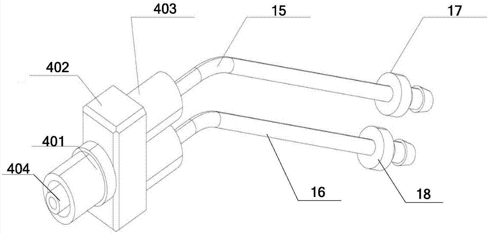
[0037] In this embodiment, the structure of the injection head is as image 3 As shown, the one-way valve 402 includes a valve body, a valve head 401 and a valve stem 403; the injection cavity 404 is arranged in the valve head 401, the rear end communicates with the output end of the valve body, and the front end is used to connect a needle; the valve stem 403 An infusion chamber is arranged inside, and the infusion tube 4 communicates with the infusion chamber; the infusion chamber communicates with the injection chamber 101 in the valve body.

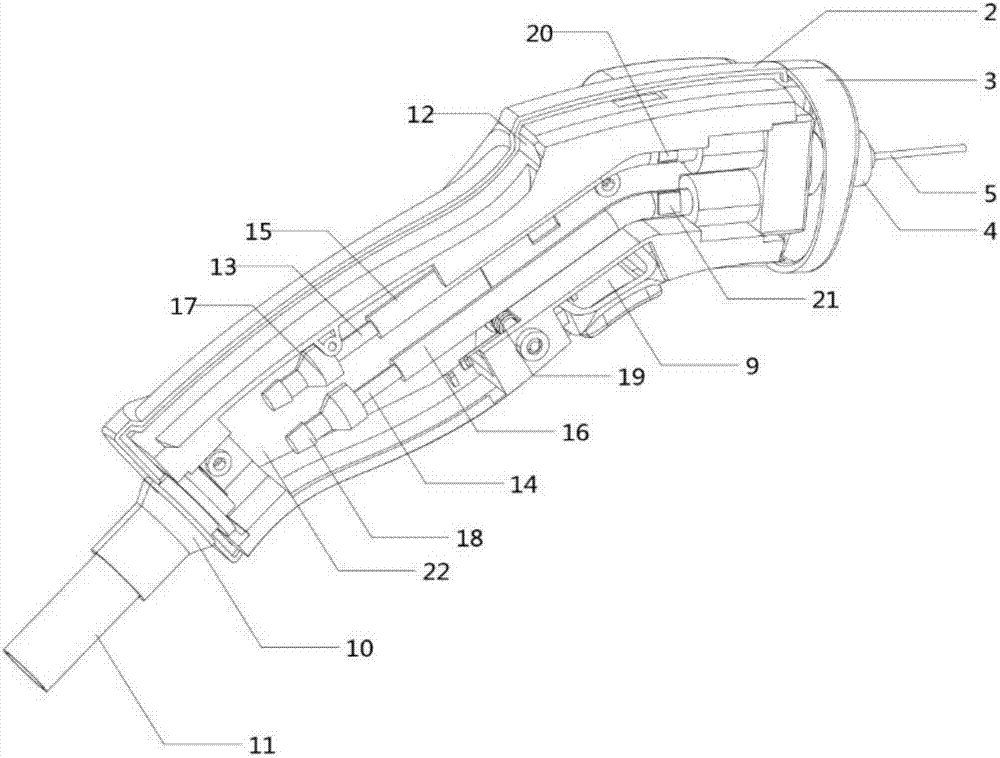
[0038] In this embodiment, two infusion tubes are provided, which are infusion tube A13 and infusion tube B14 respectively, and the ends of the infusion tube A13 and infusion tube B14 are provided with a hose connector A17 and a hose connector B18 respectively. The infusion tube A13 and the infusion tube B14 are covered with a heating element; the heating element is preferably a heating wire A15 and a heating wire B16. The infusion t...

Embodiment 2

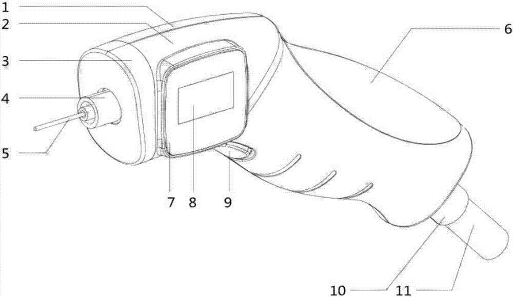
[0040] The shell is spliced ​​by the front shell 2 and the rear shell 1, and the front shell 2 and the rear shell 1 are assembled by internal fixing parts, which are light in weight and easy to carry; the grip part and the injection part are designed in line with ergonomics, Greatly facilitate the injection operation.

[0041] A circuit board 22 connected to the heating assembly and a temperature sensor is arranged in the casing, and a trigger switch 9 is arranged at the bottom of the grip part 6 of the casing. The trigger switch 9 contacts the circuit board 22 through a switch spring 19, and triggers the Injection action. The injection trigger switch can realize the electronically controlled trigger injection of the dual-line injection handle, which greatly reduces the work intensity of the user. At the same time, the injection trigger switch is used for inductive injection, which is convenient to use and has a higher degree of intelligence;

[0042] A display assembly 7 is ...

Embodiment 3

[0044] This embodiment takes double infusion tubes as an example to illustrate the injection process of the portable injection handle of the present invention. The ends of the infusion tube A13 and the end of the infusion tube B14 are respectively provided with a hose connector A17 and a hose connector B18. The tube connector B18 gathers the infusion tubes A and B at the rear of the casing to the casing 11, and the casing 11 passes through the rear end of the grip part 6 of the casing, and the casing 11 is connected to a driving device, such as a peristaltic pump, a plunger Pumps, etc., the injection actions of the two infusion tubes are controlled by their respective driving devices. Through the program setting of the driving devices, the practical injection actions include:

[0045] 1. Inject A vaccine;

[0046] 2. Inject B vaccine;

[0047] 3. Simultaneous injection of vaccines A and B;

[0048] 4. Inject A vaccine first, followed by B vaccine;

[0049] 5. Inject B vacci...


PUM


Abstract

The invention provides an injection device. The injection device comprises a shell body and an injection head which is disposed inside the shell body, wherein the injection head includes a one-way valve, an injection cavity which is communicated with the output end of the one-way valve, and at least two infusion tubes which are communicated with the input end of the one-way valve and gather in the injection cavity inside the one-way valve; the shell body includes a gripping part and an injection part, and the injection cavity stretches out of the injection part of the shell body and is removably connected with a syringe needle. The injection device is provided with a portable injection handle, and the whole shell body is jointly formed by a double-layer shell body, thereby the injection device is light in weight and easy to carry; a plurality of infusion tubes are communicated with the input end of the one-way valve, thereby the injection device can achieve a simultaneous mixed injection or a continuous injection in a specific order of a plurality of vaccines; simultaneously, the vaccines flow in one direction isolated-inside the infusion tubes, an infusion cavity, the one-way valve and the injection cavity, thereby resolving the backflow, contamination and leakage of the vaccines; besides, a heating component and a temperature sensor are arranged outside the infusion tubes, thereby the temperature of the vaccines can be controlled at any time and the injection quality is improved.

Description

technical field [0001] The present invention relates to the technical field of injection devices, in particular to an injection device. Background technique [0002] Vaccination can be used to prevent and / or reduce the impact of disease on poultry. In most poultry vaccination situations, many individuals need to be vaccinated at substantially the same time, sometimes in the hundreds or even thousands. [0003] At present, the commonly used method is manual injection inoculation. Manual inoculation requires one hand to grasp poultry, and the other hand to inject with a syringe. Traditional syringes are mostly manual mechanical syringes. There are great defects in the operation process: [0004] 1. The existing manual mechanical syringe is heavy and inconvenient to carry; [0005] 2. The types of vaccines injected by syringes are relatively single, and it is impossible to inject two vaccines at the same time or sequentially. If two vaccines need to be injected, it needs to b...

Claims


Application Information

Patent Timeline
Patent Type & Authority Applications(China)
IPC IPC(8): A61D7/00
CPCA61D7/00
Inventor 杨晓梅
Owner 青岛澳德思瑞智能免疫技术有限公司
Learn More