
Mechanical lower forging extrusion and material ejection device of forging mechanical press
A technology of mechanical presses and ejector devices, which is applied to swage presses, upsetting presses, forging/pressing/hammer devices, etc., which can solve the problems of increasing production costs, reducing production efficiency, and being unable to adjust the output force of mechanical ejectors And other issues
- Summary
- Abstract
- Description
- Claims
- Application Information
AI Technical Summary
Problems solved by technology
Method used
Image

Examples
Embodiment Construction
[0038] In order to clearly illustrate the technical features of this solution, the present invention will be described in detail below through specific implementation modes and in conjunction with the accompanying drawings.
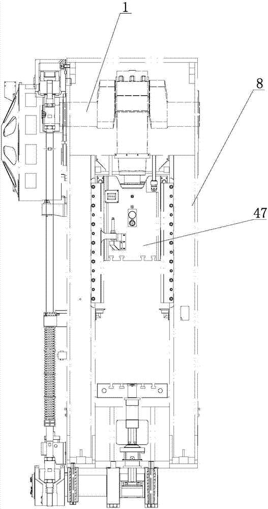
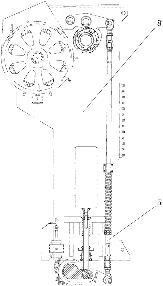
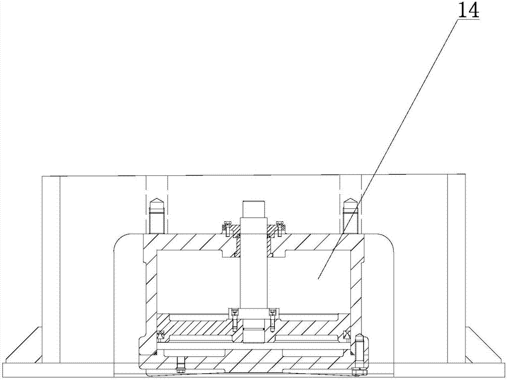
[0039] Such as Figure 4-11As shown, a forging mechanical press mechanical lower forging and ejecting device includes a crankshaft 1 arranged on a fuselage 8, an eccentric sleeve 20 is installed on one end of the crankshaft 1 through the fuselage 8, and a connecting sleeve 20 is installed on the eccentric sleeve 20. Rod 18, the lower end of connecting rod 18 is hinged with upper rod 2, the lower end of upper rod 2 is connected with lower rod 5 through disc spring 28, the lower end of lower rod 5 is hinged with one end of lever 7, upper rod 2 and lower rod 5 are installed on bracket 4 respectively Above, the bracket 4 is connected to the fuselage 8, and the middle part of the lever 7 is provided with an elongated hole 41, and the third pin shaft 32 is inst...
PUM
 Abstract
Description
Claims
Application Information