
Novel hydraulic tailstock mandrel structure

A hydraulic tailstock and mandrel technology, applied in tailstock/top, turning equipment, tool holder accessories, etc., can solve the problems of cumbersome installation, large space requirements, and complicated mechanism, so as to reduce processing costs and ensure complete travel control, high degree of automation

Inactive Publication Date: 2017-12-15
英伟达(江苏)机床有限公司
View PDF10 Cites 3 Cited by
  • Summary
  • Abstract
  • Description
  • Claims
  • Application Information

AI Technical Summary

Problems solved by technology

Built-in type, the mandrel oil cylinder is integrated into the tailstock, the mechanism is complex, the requirements for parts are high, and the installation is cumbersome
And there is no position record and control; the integral push tailstock requires a large space at the bottom of the tailstock, and is not suitable for machine tools with large strokes (the tailstock has a large stroke, and the hydraulic cylinder that is integrally pushed at the bottom is too long to be arranged)

Method used


Image

  • Novel hydraulic tailstock mandrel structure
  • Novel hydraulic tailstock mandrel structure
  • Novel hydraulic tailstock mandrel structure

Examples


Embodiment

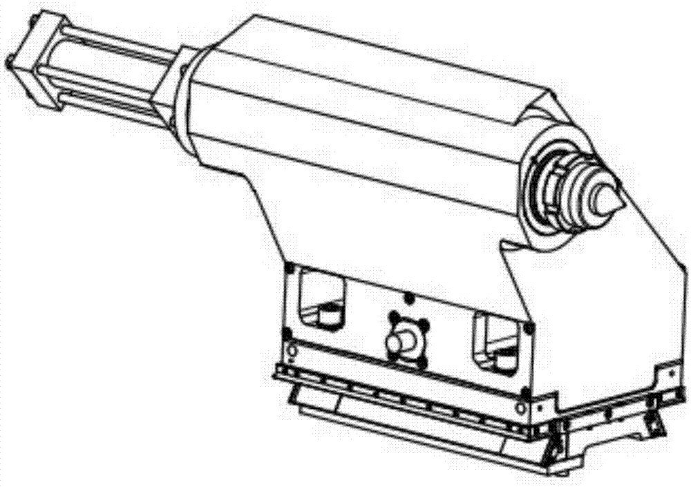
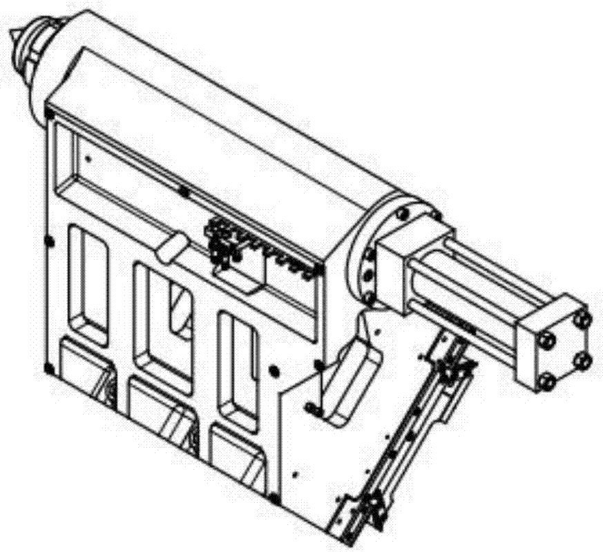
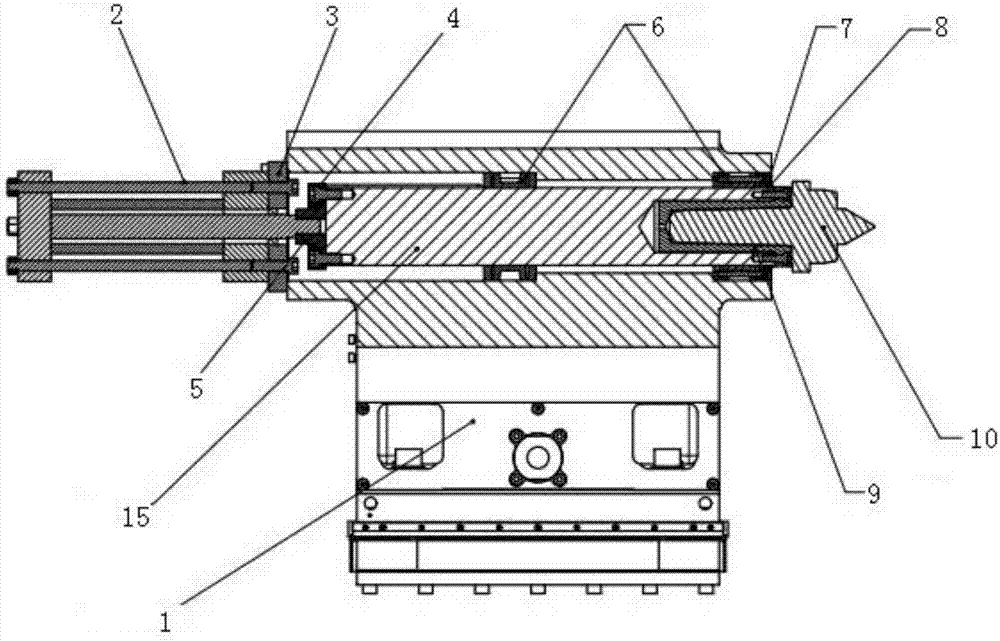
[0018] Such as Figure 1-4 As shown, a new hydraulic tailstock mandrel structure, including tailstock body 1, tailstock cylinder 2, cylinder flange 3, mandrel flange 4, piston connecting nut 5, guide sleeve 6, retaining ring 7, scraper 8. Top sleeve 9, top 10, T-shaped block 11, reading ruler 12, proximity switch bracket 13, proximity switch 14, mandrel 15 and bolt 16.

[0019] A guide sleeve 6 is fixedly installed on the tailstock body 1 , and a mandrel 15 is housed in the guide sleeve 6 .

[0020] A top sleeve 9 is fixedly installed on the head of the mandrel 15, and a top 10 is arranged in the top sleeve 9, and a retaining ring 7 and a scraper 8 are installed to complete the telescopic structure of the tailstock.

[0021] A tailstock oil cylinder 2 is fixedly installed at the tail of the mandrel 15, and the oil cylinder flange 3 and the mandrel flange 4 are sleeved on the tailstock oil cylinder 2 in sequence, and the piston connecting nut 5 is screwed on the oil cylinder p...


PUM


Abstract

The invention discloses a novel hydraulic tailstock mandrel structure, which comprises a tailstock body, a tailstock oil cylinder, a cylinder flange, a mandrel flange, a piston connection nut, a guide sleeve, a retaining ring, a scraper, a top sleeve, a top, T-blocks, reading rulers, proximity switch brackets, proximity switches, mandrels and bolts. The structure of the novel hydraulic tailstock mandrel of the present invention is simpler than that of conventional tailstock mandrels, and the requirements for parts are greatly reduced, thereby reducing the processing cost; at the same time, the installation is more convenient, the degree of automation is higher, and the stroke is completely controllable.

Description

technical field [0001] The invention belongs to the field of numerically controlled horizontal lathes, and in particular relates to a novel hydraulic tailstock mandrel structure for moving and controlling the tailstock mandrel. Background technique [0002] The hydraulic tailstock of the current CNC lathe usually adopts the built-in type or the integral push type. Built-in type, the mandrel oil cylinder is integrated into the tailstock, the mechanism is complex, the requirements for parts are high, and the installation is cumbersome. And there is no position record and control; the integral push tailstock requires a large space at the bottom of the tailstock, and is not suitable for machine tools with large strokes (the tailstock has a large stroke, and the hydraulic cylinder that is integrally pushed at the bottom is too long to be arranged). Contents of the invention [0003] Purpose of the invention: In order to solve the deficiencies of the prior art, the present inve...

Claims


Application Information

Patent Timeline
Patent Type & Authority Applications(China)
IPC IPC(8): B23B23/04
CPCB23B23/045
Inventor 张俊杰陈浩
Owner 英伟达(江苏)机床有限公司
Learn More