Long-wave infrared zoom lens unit

A zoom lens and long-wave infrared technology, applied in the field of long-wave infrared zoom lenses, can solve the problems that the details of objects cannot be clearly displayed, the range of temperature changes in the use environment is small, and there is no super wide field of view, and the thermal expansion coefficient can be achieved. Small, reduce the phenomenon of image plane drift, and compensate the effect of thermal difference

Active Publication Date: 2017-12-15
NINGBO SUNNY INFRARED TECH COMPANY
View PDF10 Cites 16 Cited by
  • Summary
  • Abstract
  • Description
  • Claims
  • Application Information

AI Technical Summary

Problems solved by technology

Because it does not have a passive heat dissipation function, it has a large volume and a small range of ambient temperature changes
[0004] In addition, the existing infrared continuous zoom lens does not have an ultra-wide field of view due to the arrangement of the lenses in the optical system and the focal length setting, and the shooting range is limited.
At the same time, the details of objects within the shooting range cannot be clearly expressed

Method used


Image

  • Long-wave infrared zoom lens unit
  • Long-wave infrared zoom lens unit
  • Long-wave infrared zoom lens unit

Examples


Embodiment 1

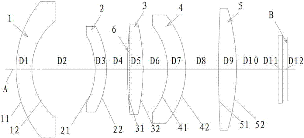
[0078] The focal length of the long-wave infrared zoom lens of the present invention is ft=8-12mm, and the F number of the optical system is FNO=1.1. The focal length of the first lens 1 is f1=-25.29mm; the focal length of the second lens 2 is f2=-50.78mm; the focal length of the third lens 3 is f3=16.74mm; the focal length of the fifth lens 5 is f5=20.85mm. BFL / ft=0.933, according to the relationship between the above-mentioned first lens 1, second lens 2, third lens 3, fifth lens 5 and the lens of the present invention, the data in Table 1 is calculated.

[0079] ft=8mm

ft=10mm

ft=12mm

f1 / ft=-3.16

f1 / ft=-2.53

f1 / ft=-2.11

f2 / ft=-6.35

f2 / ft=-5.08

f2 / ft=-4.23

f3 / ft=2.09

f3 / ft=1.67

f3 / ft=1.40

f5 / ft=2.61

f5 / ft=2.09

f5 / ft=1.74

[0080] Table I

[0081] In this embodiment, the specific parameters of the first lens 1, the second lens 2, the third lens 3, the fourth lens 4, and the fifth lens 5 are sho...

Embodiment 2

[0100] The focal length of the long-wave infrared zoom lens of the present invention is ft=8-12mm, and the F number of the optical system is FNO=1.1. The focal length of the first lens 1 is f1=-20.67mm; the focal length of the second lens 2 is f2=-24.61mm; the focal length of the third lens 3 is f3=12.03mm; the focal length of the fifth lens 5 is f5=16.78mm. BFL / ft=0.734, according to the relationship between the above-mentioned first lens 1, second lens 2, third lens 3, fifth lens 5 and the lens of the present invention, the data in Table 6 is calculated.

[0101] ft=8mm

ft=10mm

ft=12mm

f1 / ft=-2.58

f1 / ft=-2.07

f1 / ft=-1.72

f2 / ft=-3.08

f2 / ft=-2.46

f2 / ft=-2.05

f3 / ft=1.50

f3 / ft=1.20

f3 / ft=1.00

f5 / ft=2.10

f5 / ft=1.68

f5 / ft=1.40

[0102] Table six

[0103] In this embodiment, the specific parameters of the first lens 1, the second lens 2, the third lens 3, the fourth lens 4, and the fifth lens 5 are s...

Embodiment 3

[0124] The focal length of the long-wave infrared zoom lens of the present invention is ft=8-12mm, and the F number of the optical system is FNO=1.1. The focal length of the first lens 1 is f1=-25.34mm; the focal length of the second lens 2 is f2=-74.49mm; the focal length of the third lens 3 is f3=17.11mm; the focal length of the fifth lens 5 is f5=17.29mm. BFL / ft=1.24 According to the relationship between the first lens 1, the second lens 2, the third lens 3, and the fifth lens 5 and the lenses of the present invention, the data in Table 11 are calculated.

[0125] ft=8mm

ft=10mm

ft=12mm

f1 / ft=-3.17

f1 / ft=-2.53

f1 / ft=-2.11

f2 / ft=-9.31

f2 / ft=-7.45

f2 / ft=-6.21

f3 / ft=2.14

f3 / ft=1.71

f3 / ft=1.43

f5 / ft=2.16

f5 / ft=1.73

f5 / ft=1.44

[0126] Table Eleven

[0127] In this embodiment, the specific parameters of the first lens 1, the second lens 2, the third lens 3, the fourth lens 4, and the fifth lens 5 ...


PUM


Abstract

The invention relates to a long-wave infrared zoom lens unit comprising a first lens, a second lens, a third lens, a fourth lens and a fifth lens that are arranged from an object side to an image side successively along an optical axis. At least two of the lenses are made of an infrared material with a low thermal expansion coefficient; and each of the lenses has at least one diffraction surface. Because of the infrared material with a low thermal expansion coefficient, the influence on the lens by the temperature change is reduced and occurrence of an image plane drift phenomenon, caused by the temperature change, of the lens is reduced. The lens has the small thermal expansion coefficient and thus the lens has the good athermalization performance, so that the long-wave infrared zoom lens can be used in a large environment with temperature changing. Meanwhile, because the lens has the athermalization performance, the athermalization performance of each lens is realized by reducing the adjusting distances between the lenses, so that the size of the long-wave infrared zoom lens unit is reduced.

Description

technical field [0001] The invention relates to a lens, in particular to a long-wave infrared zoom lens. Background technique [0002] Because the imaging principle of infrared thermal imaging lens is different from that of visible light, it utilizes the thermal radiation imaging of the measured object itself, so that its use will not be disturbed by the external environment, and it can be used in harsh environments such as rain, snow, smog, and heavy fog. With the continuous advancement of semiconductor technology in recent years, the cost of uncooled detectors has been continuously reduced by reducing the pixel size and improving sensitivity, and the scope of use has become wider and wider, making infrared thermal imaging systems gradually develop from military to civilian use. [0003] Ordinary continuous zoom lenses change the focal length by moving the zoom group and the compensation group to achieve observation at different distances, but there is also a shortcoming, t...

Claims


Application Information

Patent Timeline
Patent Type & Authority Applications(China)
IPC IPC(8): G02B13/00G02B13/06G02B13/14G02B13/18
CPCG02B13/0045G02B13/008G02B13/06G02B13/14G02B13/18
Inventor 朱光春任和奇
Owner NINGBO SUNNY INFRARED TECH COMPANY
Why Eureka
Try Eureka