LNG tank box assembly line filling system

An assembly line and tank container technology, applied in the direction of electrical program control, sequence/logic controller program control, etc., can solve the problems of low manual operation efficiency, low degree of automation, low filling efficiency, etc., to improve filling efficiency and filling safety, reduce human error, and realize the effect of full automation

Active Publication Date: 2017-12-15
CHINA NAT OFFSHORE OIL CORP +1
View PDF9 Cites 13 Cited by
  • Summary
  • Abstract
  • Description
  • Claims
  • Application Information

AI Technical Summary

Problems solved by technology

At present, the filling of LNG tanks is mainly transported to the LNG tanker filling position by traction flatbed trucks, and the filling is performed manually by personnel. The operation process is time-consuming and laborious, the filling efficiency is low, and the safety hazard is great.
As a result, the filling efficiency of LNG tanks is far lower than that of LNG tankers, which has seriously affected the logistics economic benefits of LNG tanks and their large-scale popularization and application
[0003] At present, the filling of LNG tanks has the following problems: 1. The operation of personnel is time-consuming and labor-intensive. Since the filling position of LNG tanks on the tractor flatbed is relatively high, the pipe fitting interface is generally higher than the operator's shoulders.
During the filling operation, the operator exerts force over his shoulder, resulting in time-consuming and labor-intensive
2. Compared with mechanical operation, the efficiency of manual operation is low, and large-scale filling is easy to cause operator fatigue, resulting in a significant drop in filling efficiency
3. Personnel misuse and fatigue operation lead to great safety hazards
4. The automation of the filling process is low, and the information collection is inconvenient

Method used


Image

  • LNG tank box assembly line filling system

Examples


Embodiment Construction

[0013] The present invention will be described in detail below in conjunction with the accompanying drawings. However, it should be understood that the accompanying drawings are provided only for better understanding of the present invention, and they should not be construed as limiting the present invention. In the description of the present invention, it should be understood that the terms "first", "second" and so on are only used for the purpose of description, and should not be understood as indicating or implying relative importance.

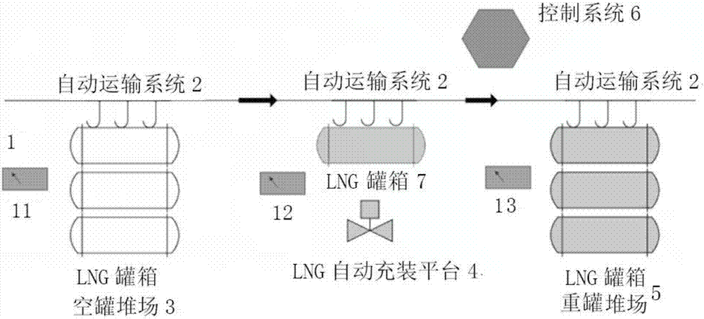
[0014] Such as figure 1 As shown, the LNG tank assembly line filling system provided by the present invention includes first to third scanners and information recorders, an automatic transportation system 2, an empty LNG tank storage yard 3, an automatic LNG filling platform 4, and an LNG tank Box heavy tank yard 5 and control system 6 .

[0015] The first to third scanning and information recorders 1 are used to obtain the ID information...


PUM


Abstract

The invention relates to an LNG tank box assembly line filling system, and the system is characterized in that the system comprises a scanning and information recorder, an LNG tank box empty tank storage yard, an automatic conveying system, an LNG automatic filling platform, a control system and an LNG tank box refilling storage yard. The scanning and information recorder is used for obtaining the recognition information of an LNG tank box before filling, during filling and after filling. The automatic conveying system is connected with the LNG tank box empty tank storage yard, the LNG automatic filling platform and the LNG tank box refilling storage yard, and is used for conveying a to-be-filled LNG tank box to sequentially pass through the LNG tank box empty tank storage yard, the LNG automatic filling platform and the LNG tank box refilling storage yard. The LNG automatic filling platform is used for completing the filling of the LNG tank box. The control system is connected with the scanning and information recorder, the automatic conveying system and the LNG automatic filling platform. The system can achieve the automatic filling of the LNG tank box, and improves the filling efficiency and safety.

Description

technical field [0001] The invention relates to an LNG tank assembly line filling system suitable for LNG receiving stations, LNG liquefaction plants, LNG satellite stations, etc., which intelligently and automatically completes the LNG tank container (also called LNG container) filling process line operation. Background technique [0002] With the rise of the third industrial revolution represented by the Internet and the improvement of intelligent logistics technology, LNG tank containers have become one of the best choices for natural gas liquid transportation. How to realize large-volume, high-efficiency, and safe filling of LNG tanks has become a hot spot in the industry. At present, the filling of LNG tanks is mainly transported to the LNG tank car filling position by traction flatbed trucks, and the filling is performed manually by personnel. The operation process is time-consuming and laborious, the filling efficiency is low, and the safety hazard is great. As a res...

Claims


Application Information

Patent Timeline
Patent Type & Authority Applications(China)
IPC IPC(8): G05B19/04
CPCG05B19/04
Inventor 谢旭光刘淼儿黄辉张燕双马政宇庄妍张莹翁然然李媛张佳宁崔艳菲
Owner CHINA NAT OFFSHORE OIL CORP
Why Eureka
Try Eureka