

Negative ion pulse intensifier
A negative ion and enhancer technology, applied in the direction of electrical components, etc., can solve the problems of short service life, complex circuit structure, small emission range, etc., and achieve the effect of long service life, long duration and fast migration speed
- Summary
- Abstract
- Description
- Claims
- Application Information
AI Technical Summary
Problems solved by technology
Method used
Image

Examples
Embodiment Construction
[0024] In order to better understand the present invention, the content of the present invention is further illustrated below in conjunction with the examples, but the content of the present invention is not limited to the following examples.
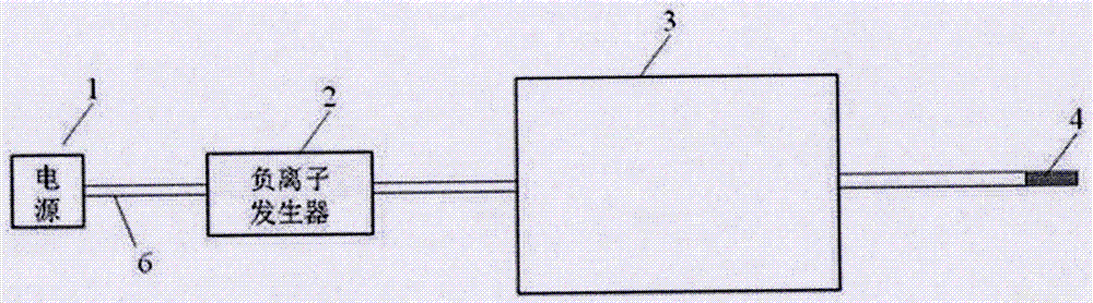
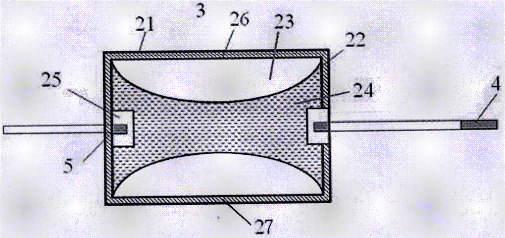
[0025] Such as figure 2 As shown, the present embodiment is a negative ion pulse intensifier, including a high-voltage insulating square shell 21, an inner shell 26, an anion generator access end and an anion accelerator release end, and the inner shell 26 is provided with a hyperbolic cross section. Shaped acceleration inner cylinder 22, the two ends of the acceleration inner cylinder 22 and the two ends of the inner casing 26 are matched and sealed, the interior of the acceleration inner cylinder 22 is filled with natural ore powder 24, and the negative ion generator access end is provided with a negative ion emitting carbon fiber. Conductor 25, conductor 25 is positioned at the central position of acceleration inner tube 22 ends, th...
PUM
 Abstract
Description
Claims
Application Information