Combined microwave sensor and dielectric constant measurement method for measured object

A technology for microwave sensors and objects to be measured, applied in measurement devices, measurement of electrical variables, measurement of resistance/reactance/impedance, etc., can solve the problems affecting the accuracy of measurement, increase the cost and difficulty of processing, etc. Wide availability, accurate measurement results

Active Publication Date: 2017-12-19
HENAN NORMAL UNIV
View PDF4 Cites 31 Cited by
  • Summary
  • Abstract
  • Description
  • Claims
  • Application Information

AI Technical Summary

Problems solved by technology

For example, the researchers used the substrate-integrated waveguide technology to excite the substrate-integrated waveguide resonator TE through the microstrip line. 101 mode to realize the measurement of material permittivity, but the measurement accuracy is affected by the background noise when planar transmission lines such as microstrip lines excite substrate-integrated waveguide resonators
Moreover, the substrate integrated waveguide resonator needs to process metal through holes on the dielectric board, which increases the cost and difficulty of processing

Method used


Image

  • Combined microwave sensor and dielectric constant measurement method for measured object
  • Combined microwave sensor and dielectric constant measurement method for measured object
  • Combined microwave sensor and dielectric constant measurement method for measured object

Examples


Embodiment Construction

[0026] The present invention will be described in further detail below with specific embodiments in conjunction with the accompanying drawings.

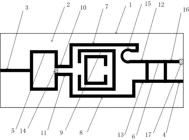
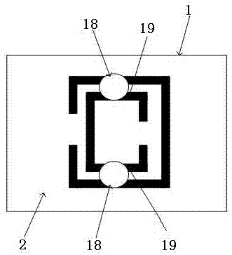
[0027] like figure 1 As shown, a composite microwave sensor is a two-port device, which consists of a metal ground 1 on the bottom layer, a medium 2 on the middle layer, and a measuring device on the top layer; the measuring device includes input port 3, output port I4, branch line coupling Device 6, power splitter 5, split resonant ring 9, 50-ohm microstrip line I7 and 50-ohm microstrip line II8.

[0028] The input port 3 and the output port I4 are connected with the vector network analyzer; the output side of the branch line coupler 6 is provided with an isolation port 16 and the output port I4; the input end of the power splitter 5 is connected with the input port 3, and the power splitter The output port II10 of 5 communicates with the port I12 of the branch line coupler 6 through the microstrip line I7; the output port III11 of...


PUM


Abstract

A combined microwave sensor comprises metal ground at the bottom layer, dielectric at the middle layer, an input port, an output port I, a branched line coupler, a power divider, an open resonant ring, a microstrip line I and a microstrip line II, wherein the input port, the output port I, the branched line coupler, the power divider, the open resonant ring, the microstrip line I and the microstrip line II are arranged in the top layer. The input port and the output port I are connected with a vector network analyzer. The output side of the branched line coupler is provided with an isolated port and the output port I. The input end of the power divider is connected with the input port. The output port II and the output port III are connected with an annular directional coupler through a microstrip line. The open resonant ring is arranged between the power divider, the branched line coupler and the two microstrip lines. The combined microwave sensor has advantages of effectively eliminating background noise, realizing testing for weak background signals, and ensuring large offset of the sensor resonant frequency through small disturbance of the tested object. Therefore the combined microwave sensor provided by the invention has higher sensitivity and higher accuracy in dielectric constant measurement and can be used in high-sensitivity testing with small dielectric constant change.

Description

technical field [0001] The invention relates to a material parameter measurement technology at a microwave frequency, in particular to a high-sensitivity composite microwave sensor for measuring the dielectric properties of a dielectric material based on a split resonator ring (SRR) and a destructive circuit, and belongs to the field of microwave measurement technology. Background technique [0002] As microwave technology is widely used in more and more industries, the measurement of dielectric constant of materials has also been greatly developed. For example, fields such as medicine, food, chemical industry and meteorology all obtain various parameters needed by measuring the dielectric properties of materials, such as humidity, temperature, density and so on. There are many methods used to measure the dielectric constant, which can be mainly divided into resonance method and non-resonance method. The resonance method has been widely used due to its high sensitivity and ...

Claims


Application Information

Patent Timeline
Patent Type & Authority Applications(China)
IPC IPC(8): G01R27/26
Inventor 刘伟娜杨新伟张满满刘长虹
Owner HENAN NORMAL UNIV
Why Eureka
Try Eureka