
Spatial structured light transmitting device

A space structure and emission device technology, which is applied in the field of space structure light emission devices, can solve the problems of increasing difficulty, reducing product performance due to processing accuracy, etc.

Active Publication Date: 2017-12-19
HUATIAN TECH KUNSHAN ELECTRONICS
View PDF23 Cites 7 Cited by
  • Summary
  • Abstract
  • Description
  • Claims
  • Application Information

AI Technical Summary

Problems solved by technology

However, each light source in the array light source has a certain arrangement direction, and the DOE such as the Damman grating is a two-dimensional structure, which is also directional. Therefore, the array light source and the Damman grating in this technical solution must meet certain requirements. The arrangement requirements of the azimuth angle increase the difficulty of production, and the processing accuracy will also reduce the performance of the product

Method used

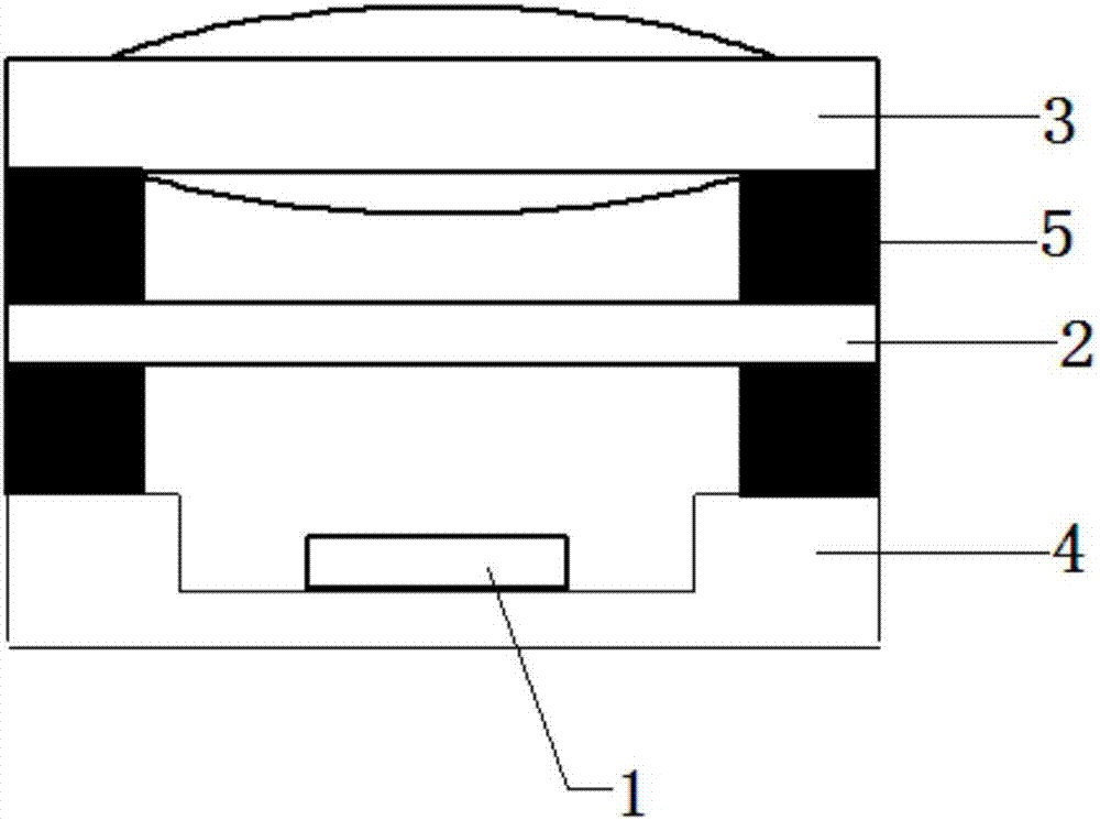
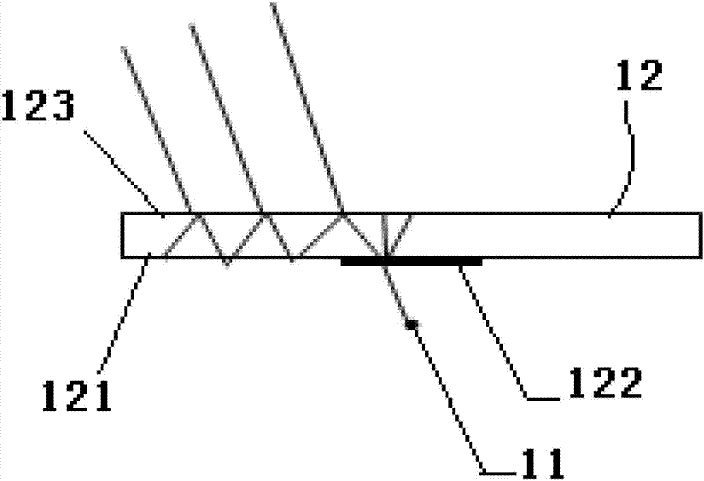

Image

  • Spatial structured light transmitting device
  • Spatial structured light transmitting device

Examples


Embodiment Construction

[0019] In order to be able to understand the technical content of the present invention more clearly, the following embodiments are specifically described in detail, the purpose of which is only to better understand the content of the present invention and not to limit the protection scope of the present invention. The various components in the structure of the drawings of the embodiment are not scaled in normal proportions, so they do not represent the actual relative size of the structures in the embodiment.

[0020] Such as figure 1 As shown, a spatially structured light emitting device includes an expanded light source 1 and a diffractive optical element 2. The expanded light source emits wide-angle incident light, and the diffractive optical element transforms and shapes the wide-angle incident light emitted by the expanded light source Structured light into the required space. It also includes a projection lens 3, the projection lens is arranged between the diffractive opti...


PUM


Abstract

The invention discloses a spatial structured light transmission device, wherein an extended light source is combined with a diffraction optical element. Optimized designing is performed on the structure parameter of the diffraction optical element, thereby forming the spatial structured light transmission device based on large-angle incident light, wherein the extended light source transmits large-angle incident light. The diffraction optical element is based on the design of a traditional diffraction element, and a designing restraint for aiming at an incident angle change is added so that the diffraction optical element is suitable for the large-angle incident light and a requirement for the effect of the required structured light can be satisfied. Compared with a traditional single-point light source, the extended light source has advantages of realizing larger light emitting area and more compact structure than that of the single-point light source, and greatly reducing device size. Compared with an array light source, the extended light source has advantages of realizing no directionality in a plane which is parallel with the diffraction optical element, reducing a production requirement, increasing tolerance and realizing lower cost.

Description

Technical field [0001] The invention relates to the technical field of structured light projection, in particular to a novel spatial structured light emitting device. Background technique [0002] The use of diffractive optical elements (DOE) for beam shaping can efficiently generate uniform light or structured light fields. It has important applications in the field of lighting or 3D reconstruction. For example, referring to patent document CN205002744U, a diffractive optical element (Daman grating or similar element) can be used as a beam splitter for an optical projector, which generates and projects multiple copies of the baseline pattern onto an object or scene. The multiple copies are angularly offset relative to each other and overlap each other. The resulting spot pattern, which includes the superposition of multiple copies of the baseline pattern, is referred to herein as a composite pattern. For the overlap between multiple copies, the pitch or density of the composi...

Claims


Application Information

Patent Timeline
Patent Type & Authority Applications(China)
IPC IPC(8): G02B27/09G03B21/20
CPCG02B27/0944G03B21/2033G03B21/208
Inventor 李凡月
Owner HUATIAN TECH KUNSHAN ELECTRONICS
Learn More