
Dual circularly polarized array antenna

A dual circular polarization and array antenna technology, applied in the electronic field, can solve the problems of high gain, isolation deviation, and insufficient compact size, etc., and achieve the effect of wide axial ratio bandwidth, high isolation, and light appearance

Active Publication Date: 2017-12-19
SOUTHEAST UNIV
View PDF5 Cites 11 Cited by
  • Summary
  • Abstract
  • Description
  • Claims
  • Application Information

AI Technical Summary

Problems solved by technology

Many dual circularly polarized antennas use a single antenna unit, which is difficult to achieve high gain;
[0005] 2. There are difficulties in the direct integration of the dual circularly polarized array antenna and the circuit, the size is not compact enough, and the shape is bulky
Some scholars have realized a dual circularly polarized array antenna with high gain by using a multilayer metal waveguide structure. Some limitations are imposed on
[0006] 3. The working frequency of dual circularly polarized antennas is generally not high
At present, the cross-polarization level of circularly polarized waves achieved by related technologies is generally within -15dB, which will affect some specific application scenarios;
[0008] 5. The isolation deviation of the two polarization excitation ports of the antenna; the polarization isolation of the relevant dual circularly polarized antennas reported so far is generally around 10dB, and the mutual influence of the two polarization ports cannot be ignored

Method used


Image

  • Dual circularly polarized array antenna
  • Dual circularly polarized array antenna
  • Dual circularly polarized array antenna

Examples


Embodiment Construction

[0038] The technical solutions and beneficial effects of the present invention will be described in detail below in conjunction with the accompanying drawings.

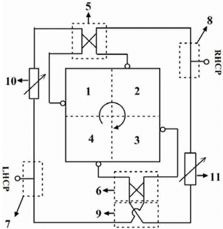
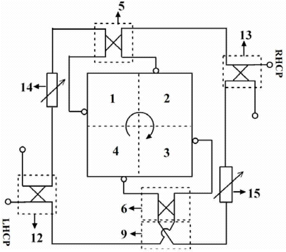
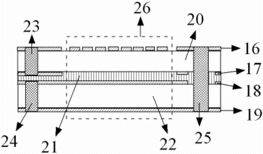
[0039] refer to figure 1 and figure 2 , the present invention provides a dual circularly polarized array antenna, comprising four radiating units 1, 2, 3, 4 and two parts of a dual circularly polarized feeding network, wherein the radiating units 1, 2, 3, 4 adopt a sequential rotation sequence The circularly polarized wave is generated in the form of two rows and two columns. The radiation unit 1 is placed as it is, the radiation unit 2 is rotated 90 degrees clockwise (or counterclockwise) around its central axis, and the radiation unit 3 is placed around its own center. The axis is rotated 180 degrees clockwise (or counterclockwise) and placed, and the radiation unit 4 is placed after it is rotated 270 degrees clockwise (or counterclockwise) around its central axis. figure 1 and figure 2 Both are examples of clo...


PUM


Abstract

The invention discloses a dual circularly polarized array antenna. The dual circularly polarized array antenna comprises a first radiation unit, a second radiation unit, a third radiation unit, a fourth radiation unit and a dual circularly polarized feeding network, wherein the first radiation unit, the second radiation unit, the third radiation unit and the fourth radiation unit are used for generating circularly polarized waves in a mode of ordered rotation sequence and are arranged in two lines and two rows, the dual circularly polarized feeding network is provided with two input ports and four output ports, feeding with equal amplitude and unequal phases is provided for the first radiation unit, the second radiation unit, the third radiation unit and the fourth radiation unit, excitation is input from the two input ports of the feeding network, so that the four output ports provide two different excitation phase distributions. By the antenna structure, the dual circularly polarized wave can be effectively generated, the dual circularly polarized wave with high gain, low cross polarization, relatively wide axial ratio bandwidth and relatively high isolation can be achieved in a millimeter wave band with relatively high frequency, and the dual circularly polarized array antenna has the characteristics of compact structure and lightness and is easy to integrate with a radio frequency front-end circuit.

Description

technical field [0001] The invention belongs to the field of electronics, in particular to a dual circular polarization array antenna. Background technique [0002] Circularly polarized waves have the characteristics of anti-rain and fog attenuation, and can interfere with any linearly polarized waves and elliptical polarized waves. Circularly polarized antennas can receive incoming waves of any polarization. Polarized waves can be received by antennas with any polarization. Due to the above-mentioned characteristics of circularly polarized waves, they are widely used in remote measurement such as remote sensing, long-distance communications such as satellite communications, radar, electronic reconnaissance and electronic interference, etc. , the circularly polarized antenna has a wide range of application scenarios. [0003] For circularly polarized antennas, experts, scholars, and engineers and technicians in related fields have carried out extensive research and formed a...

Claims


Application Information

Patent Timeline
IPC IPC(8): H01Q1/38H01Q1/50H01Q21/00H01Q21/24
CPCH01Q1/38H01Q1/50H01Q21/0006H01Q21/24
Inventor 洪伟徐俊蒋之浩陈继新张慧
Owner SOUTHEAST UNIV
Learn More