Mechanical brake control apparatus, method and system of pumping storage unit

A technology of mechanical braking and control devices, applied in control systems, mechanical equipment, safety devices, etc., can solve problems such as equipment damage, equipment damage, direct and indirect economic losses, etc.

Pending Publication Date: 2017-12-19
STATE GRID CORP OF CHINA +3
View PDF6 Cites 13 Cited by
  • Summary
  • Abstract
  • Description
  • Claims
  • Application Information

AI Technical Summary

Problems solved by technology

[0003] Pumped-storage power stations have experienced equipment damage accidents caused by mechanical braking in the direction of power generation of the unit; there have also been incidents where the circuit breaker (hereinafter referred to as GCB) at the outlet of the generator motor of the unit was separated during shutdown, and the movable guide vanes were fully closed due to speed measurement. The abnormal signal of the device leads to high-speed braking and equipment damage accidents; the latest phenomenon is that when the water pump of a pumped-storage power station in a pumped-storage power station is powered off and shut down, due to the characteristics of the unit itself, the unit speed will stop from 100% to zero. Reverse to a higher speed

Method used


Image

  • Mechanical brake control apparatus, method and system of pumping storage unit
  • Mechanical brake control apparatus, method and system of pumping storage unit
  • Mechanical brake control apparatus, method and system of pumping storage unit

Examples


Embodiment Construction

[0093] The following will clearly and completely describe the technical solutions in the embodiments of the present invention with reference to the accompanying drawings in the embodiments of the present invention. Obviously, the described embodiments are only some, not all, embodiments of the present invention. Based on the embodiments of the present invention, all other embodiments obtained by persons of ordinary skill in the art without making creative efforts belong to the protection scope of the present invention.

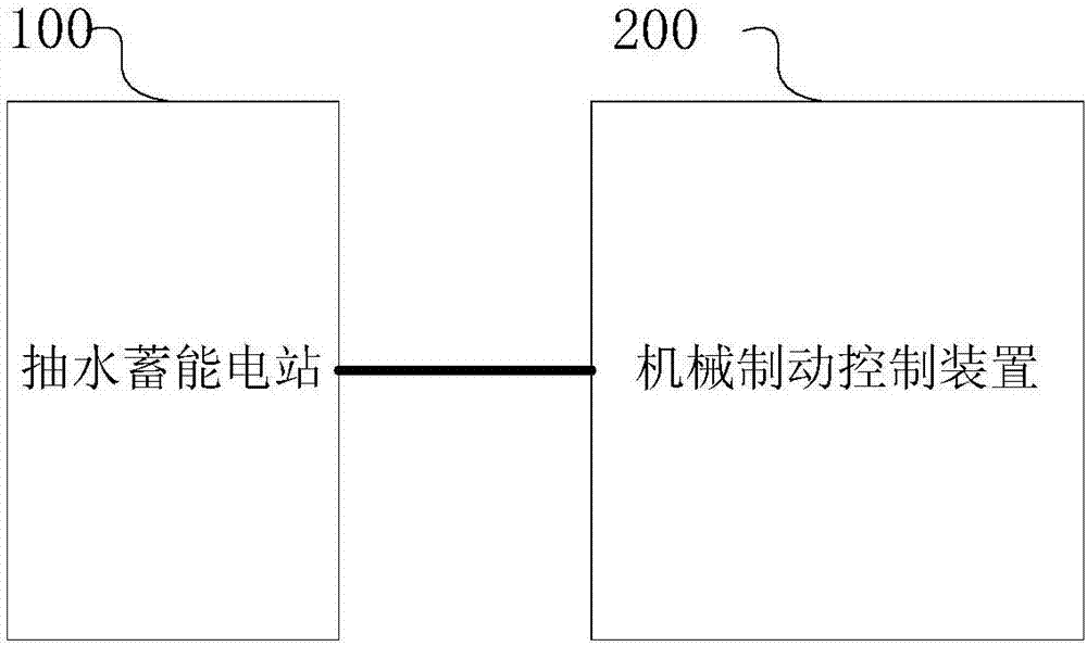
[0094] figure 1 For a structural schematic diagram of a mechanical brake control system of a pumped-storage unit provided by the present invention, please refer to figure 1 , the system provided by the present invention includes a pumped storage power station 100 and a mechanical brake control device 200 of the pumped storage unit.

[0095]In the prior art, pumped storage power stations are generally designed with corresponding mechanical brake control device...


PUM


Abstract

The invention provides a mechanical brake control apparatus, method and system of a pumping storage unit. The method comprises the steps of outputting a mechanical brake instruction according to a feedback signal of an electric brake disconnecting link in a water pumping energy storage power station, a feedback signal of a GCB, a feedback signal of a guide vane all-off sensor, a rotary speed signal of a unit, a feedback signal of a guide vane opening feedback sensor, a rotary speed signal measured by a fluted disc speed measurement probe, a first rotary speed threshold value and a second rotary speed threshold value, to enable an electromagnetic valve to act to control the low-pressure gas in a mechanical brake air supply pipeline to enter a lower cavity of the electromagnetic valve through linkage of the electromagnetic valve and to jack the lower cavity, and enabling a brake ring which is fixed below a rotation part of a unit generator motor of the water pumping energy storage power station to be in friction, so as to enable the pumping storage unit of the water pumping energy storage power station to be stopped in a static state. By virtue of addition of the speed regulator, the feedback signal of the guide vane opening feedback sensor and the rotary speed signal measured by the fluted disc speed measurement probe are electrically adjusted and collected to be used as the input mechanical brake conditions, so that reliability of a signal circuit can be improved.

Description

technical field [0001] The present invention relates to the technical field of power systems, in particular to the technical field of pumped-storage power stations in power systems, and specifically relates to a novel mechanical brake control device, method and system for pumped-storage units. Background technique [0002] At present, pumped storage power stations are designed with mechanical brake control devices, commonly known as mechanical brakes or brakes, and mechanical brake control devices are one of the necessary auxiliary control equipment for hydropower stations and pumped storage power stations. When the unit is shut down, the speed is lower than a certain speed, and the brake is put into the brake, which rubs against the brake ring fixed at the bottom of the generator motor, so as to stop the pumped storage unit to a static state and no longer rotate. After the unit has come to a complete stop, the brake can be selected to be engaged all the time, or it can be w...

Claims


Application Information

Patent Timeline
IPC IPC(8): H02P3/04F03B13/06F03B15/00H02P101/10
CPCH02P3/04F03B13/06F03B15/00H02P2101/10Y02E10/20Y02E60/16
Inventor 邓磊吕滔唐拥军周攀刘锋高翔刘仁张飞王庭政秦俊周喜军杨洪涛熊涛散齐国徐利君朱文娟赵博邓拓夫魏欢周健王书华王康生
Owner STATE GRID CORP OF CHINA
Why Eureka
Try Eureka