
Whole concrete stirring and conveying work platform

A working platform and concrete technology, which is applied in mixing plants, mixing operation control, clay preparation equipment, etc., can solve the problems of safety accidents, large floor area, and affecting the success of construction, so as to facilitate installation and transportation, improve construction efficiency, Simple and compact equipment

Pending Publication Date: 2017-12-22
ZHEJIANG HUA YUN OFFSHORE ENG & TECH SERVICE CO LTD
View PDF5 Cites 3 Cited by
  • Summary
  • Abstract
  • Description
  • Claims
  • Application Information

AI Technical Summary

Problems solved by technology

[0002] At present, most of the existing concrete construction platforms are composed of temporary splicing of concrete mixing equipment and conveying equipment on site, which covers a large area and has many components, which makes installation and transition more cumbersome and time-consuming. The particularity of large-capacity grouting construction and the high requirements of high-strength grouting materials on equipment performance, high risk factor and inability to cope with various emergencies that may occur during construction, resulting in discontinuous or even interruption of grouting construction, prone to grouting quality problems , while the quality of grouting directly affects the overall stability and safety of the structure
[0003] Concrete grouting construction is an irreversible construction link. Once it fails, it will be difficult to repair, which will directly affect the success or failure of the entire construction, and will also affect the dispatch cost and construction period of construction equipment.
Therefore, once there is a problem with the grouting quality, it will cause huge losses and may cause safety accidents

Method used


Image

  • Whole concrete stirring and conveying work platform
  • Whole concrete stirring and conveying work platform
  • Whole concrete stirring and conveying work platform

Examples


Embodiment 1

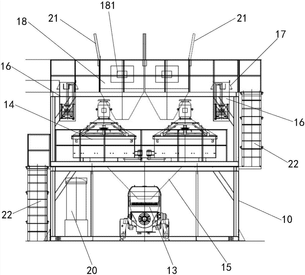
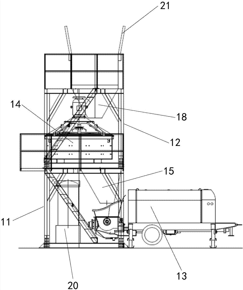
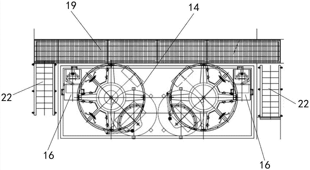
[0044] like Figure 1-7 As shown, the overall working platform for concrete mixing and conveying provided in this embodiment includes a frame 10, at least one conveying pump 13, at least one agitator 14 and a control system;

[0045] like Figure 4-7As shown, the frame 10 includes a first layer of support 11 and a second layer of support 12, the frame 10 is a frame structure, including horizontal members, vertical members and braces welded, such as Figure 6-7 As shown, there are brackets installed around the bottom of the first layer of bracket 11, which are used for temporary fixing by welding during construction, and as shown in Figure 4-5 As shown, the bottom and top of the second layer of support 12 are equipped with detachable railings. The second layer of support 12 is located above the first layer of support 11, and the agitator 14 is arranged on the second layer of support 12. , the agitator 14 is connected to the second layer of support 12 by bolts, and fixed on t...


PUM


Abstract

The invention relates to the technical field of concrete stirring and conveying, in particular to a whole concrete stirring and conveying work platform. The whole concrete stirring and conveying work platform comprises a rack, at least one conveying pump, at least one stirring device and a control system; the rack is provided with a first layer support and a second layer support; the stirring device is arranged on the second layer support, a feeding cylinder and a water supply system are arranged at the position corresponding to an inlet of the stirring device, and the water supply system can convey stirring water to the stirring device; a discharging hopper is arranged at the top of the first layer support, an inlet of the discharging hopper corresponds to a discharging opening of the stirring device, the conveying pump is arranged below the discharging hopper, and therefore concrete in the discharging hopper can flow into the conveying pump; the control system is connected with the stirring device, the conveying pump and the water supply system. According to the scheme, modular integration design is adopted, whole lifting can be achieved, grouting construction can be continuously achieved for a long time, smooth construction can be effectively ensured, manpower is saved, and construction efficiency is improved.

Description

technical field [0001] The invention relates to the technical field of concrete mixing and conveying, in particular to an integral working platform for concrete mixing and conveying. Background technique [0002] At present, most of the existing concrete construction platforms are composed of temporary splicing of concrete mixing equipment and conveying equipment on site, which covers a large area and has many components, which makes installation and transition more cumbersome and time-consuming. The particularity of large-capacity grouting construction and the high requirements of high-strength grouting materials on equipment performance, high risk factor and inability to cope with various emergencies that may occur during construction, resulting in discontinuous or even interruption of grouting construction, prone to grouting quality problems , and the quality of grouting directly affects the overall stability and safety of the structure. [0003] Concrete grouting constr...

Claims


Application Information

Patent Timeline
IPC IPC(8): B28C9/02B28C7/14B28C7/16B28C7/12B28C7/06
CPCB28C7/064B28C7/122B28C7/14B28C7/163B28C9/02
Inventor 朱荣华田振亚周晋阳曲励勃白利军陈文杰
Owner ZHEJIANG HUA YUN OFFSHORE ENG & TECH SERVICE CO LTD
Learn More