Eureka AIR delivers breakthrough ideas for toughest innovation challenges, trusted by R&D personnel around the world.

Classification and bin separation type garbage automatic collection system

A technology of automatic collection and garbage collection, applied in garbage collection, trash can, garbage cleaning, etc., can solve the problems of unpleasant odor, imperfect design, high cost, reduce explosion risk, avoid secondary pollution, improve The effect of suction efficiency

Inactive Publication Date: 2017-12-22
福建海山机械股份有限公司
View PDF8 Cites 1 Cited by
  • Summary
  • Abstract
  • Description
  • Claims
  • Application Information

AI Technical Summary

Problems solved by technology

[0004] 1. The system is prone to jamming: when there are large-volume and long-sized garbage that is not conducive to pipeline transportation, such as discarded wine bottles, basins, bowls, shovels, spoons, etc. There is no mechanism that can break the garbage into small pieces, and it is easy to get stuck in the storage section, discharge valve or delivery pipeline, etc., resulting in problems such as blockage of the storage section, failure of the discharge valve, and poor negative pressure formation in the delivery pipeline, which in turn leads to system not working
[0005] 2. There is a hidden danger of explosion in this system: when garbage containing kitchen soup is put into the garbage disposal port and falls to the storage section, it will not only easily pollute the garbage disposal port, storage section, and discharge valve, but also emit an unpleasant odor (the main The composition is methane), and due to the poor air circulation in the storage section, the methane content accumulates higher and higher. When the methane content reaches 5-15.4%, once someone throws an open flame such as an unextinguished cigarette butt into the storage section, it will happen immediately violent explosion
[0006] 3. The system does not carry out garbage classification: the system design is not perfect, and there is no garbage classification treatment mechanism; in the process of use, people completely mix and dump different types of garbage, such as kitchen waste, construction waste, domestic waste, etc., into the same garbage There is no sorting of garbage at the discharge port, and there is no classified storage in the storage section, so that the recyclable waste in the garbage is not easy to be recycled again, resulting in a waste of resources
[0007] And China's invention patent discloses a kind of vacuum pipeline garbage collection and transportation system whose patent number is CN1847110A, its system structure mainly includes three parts: the indoor garbage collection part that is made up of garbage feeding door, indoor garbage pipeline, indoor garbage temporary storage, The outdoor garbage collection part is composed of outdoor garbage feeding door, outdoor garbage pipeline, outdoor garbage temporary storage, and is composed of garbage collection separator, centrifugal fan, garbage compressor, garbage transfer vehicle, deodorization, dust removal and deodorization device, and central control room The central garbage collection station part; although the system subverts the traditional garbage collection methods and means, the entire collection and transportation process does not require manual contact, and realizes the fully enclosed and automatic collection of garbage to meet the needs of environmental protection; however, in addition to the above-mentioned closed In addition to the problems existing in the traditional automatic garbage collection system, there are also the problems of high system cost and low cost performance: for small-scale and scattered communities, the adoption of this system is not only an improvement in the length of the underground garbage pipe network connected between the communities In addition to the high cost of construction, and the need to build a central garbage collection station, it takes up a lot of land resources and has low cost performance, which cannot meet market demand

Method used


Image

  • Classification and bin separation type garbage automatic collection system
  • Classification and bin separation type garbage automatic collection system

Examples


Embodiment Construction

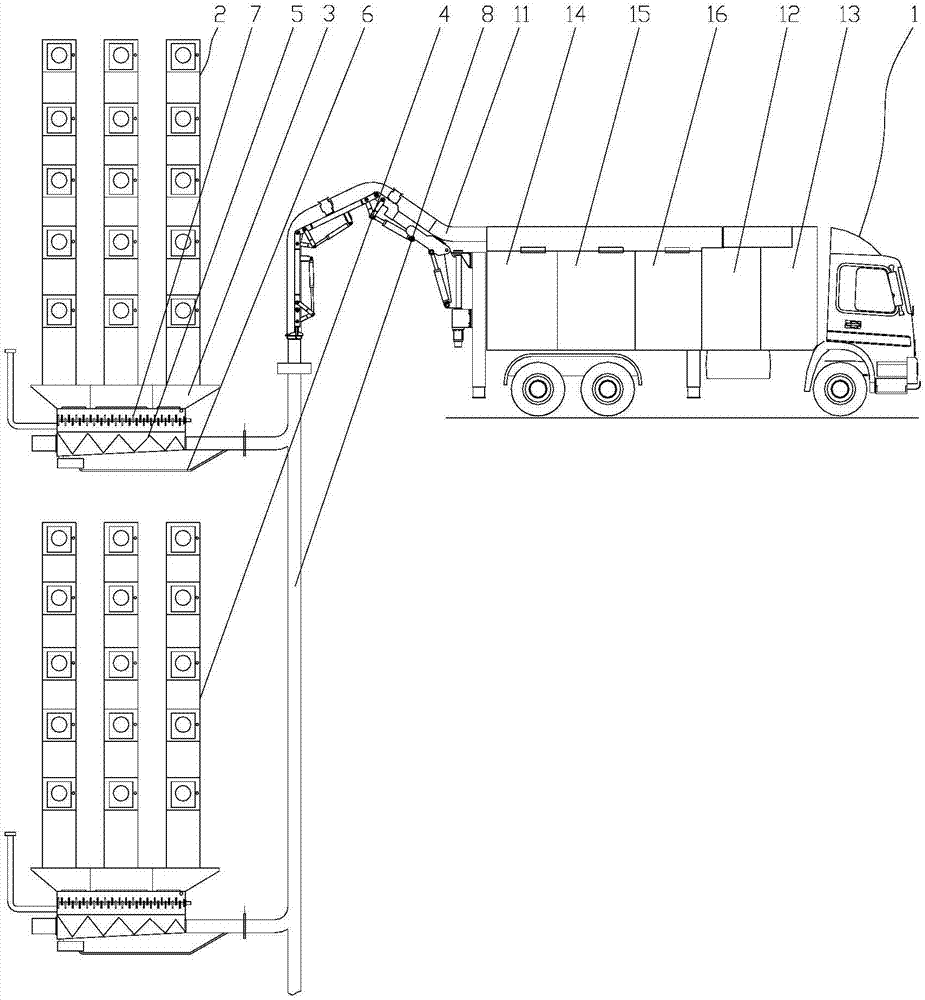
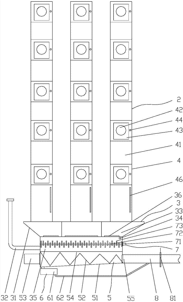
[0029] Such as figure 1 or figure 2 As shown, the automatic collection system for classified and binned garbage of the present invention includes a control center (not shown in the figure), an aerodynamic suction vehicle 1 and more than two garbage collection devices 2, and between the two or more garbage collection devices The control center communicates with the aerodynamic suction vehicle 1 and the garbage collection device 2 respectively through the suction pipeline, and is used to control the aerodynamic suction vehicle 1 and the garbage collection device 2 to perform operations. The garbage collection device 2 includes A garbage storage mechanism 3, three garbage delivery mechanisms 4 and a laid suction pipe network 8, the three garbage delivery mechanisms 4 are all located above the garbage storage mechanism 3, and the three garbage delivery mechanisms 4 are respectively used for putting in and transporting For recyclable garbage, non-recyclable garbage and other garb...


PUM


Abstract

The invention relates to a classification and bin separation type garbage automatic collection system which comprises a control center, an air power suction car and two or more garbage collection devices. The control center is connected with the air power suction car and the garbage collection devices. Each garbage collection device comprises a garbage storage mechanism, three garbage throwing mechanisms and a suction pipe net. The three garbage throwing mechanisms of each garbage collection device are used for throwing and conveying recoverable garbage, unrecoverable garbage and other garbage to be judged correspondingly. Three storage bins correspondingly communicating with the corresponding three garbage throwing mechanisms are arranged on the upper portion of each garbage storage mechanism. A transition bin communicating with the corresponding three storage bins is arranged on the lower portion of each garbage storage mechanism. The air power suction car is provided with a suction arm, a recoverable bin, an unrecoverable bin, a bin for other garbage, vacuumizing equipment and deodorization equipment. The suction arm communicates with a spiral pushing mechanism of each garbage collection device through the corresponding suction pipe net.

Description

technical field [0001] The invention relates to the technical field of garbage collection, in particular to a sorting and bin-type garbage automatic collection system. Background technique [0002] The traditional method of manual garbage collection is: a trash can is placed in the elevator room or corridor passage of each floor for residents to put in garbage, and the garbage is temporarily stored in this trash can until the sanitation workers come to collect and transport the garbage away; in some In old towns or streets, some garbage carts or large garbage bins are used to load garbage, which not only causes a strong odor around, seriously pollutes the surrounding air, but also requires sanitation workers to collect the garbage together again and transport it to the garbage Centralized processing center. These traditional methods of manually collecting garbage are not only time-consuming and labor-intensive, but also cause secondary pollution of garbage. [0003] In res...

Claims


Application Information

Patent Timeline
Patent Type & Authority Applications(China)
IPC IPC(8): B65F9/00B65F1/10B65F1/00B65F3/00B65F7/00
CPCB65F1/0053B65F1/10B65F3/001B65F7/005B65F9/00Y02W30/10
Inventor 黄向阳陈明林
Owner 福建海山机械股份有限公司
Why Eureka
Eureka Blog
Learn More