Staggered stacking structure for heat exchange pipes

A technology of heat exchange tubes and horizontal tubes, applied in the field of staggered superposition structure of heat exchange tubes, can solve problems such as temperature measurement error, uneven temperature distribution, unsuitable heat release, etc., and achieve the effect of avoiding local stress

Inactive Publication Date: 2017-12-22
贺迈新能源科技(上海)有限公司
View PDF5 Cites 4 Cited by
  • Summary
  • Abstract
  • Description
  • Claims
  • Application Information

AI Technical Summary

Problems solved by technology

[0003] 1. When charging, the phase change material will expand from solid to liquid in a certain proportion, so it is not suitable to start charging from the bottom of the device. Generally, the heating process requires the heat source to flow from top to bottom, while the phase change material flows from top to bottom during the heat release process. There is a certain proportion of contraction when the liquid becomes solid, so it is not suitable to release heat from the upper part of the device. Generally, the heat release process requires the cold source to flow from the bottom to the top. The different requirements of the two processes for the flow direction increase the difficulty of piping layout. reduce the cost of system control;
[0004] 2. The temperature distribution of the phase change energy storage device is uneven during the heat exchange process, especially the temperature difference between the upper and lower sides is large. When the device reaches a certain height, the excessive temperature difference during the heat exchange process will affect the thermodynamic characteristics of the energy storage device, and it will also be more It is easy to cause temperature measurement error

Method used


Image

  • Staggered stacking structure for heat exchange pipes
  • Staggered stacking structure for heat exchange pipes
  • Staggered stacking structure for heat exchange pipes

Examples


Embodiment Construction

[0024] Below in conjunction with accompanying drawing and embodiment the present invention will be further described:

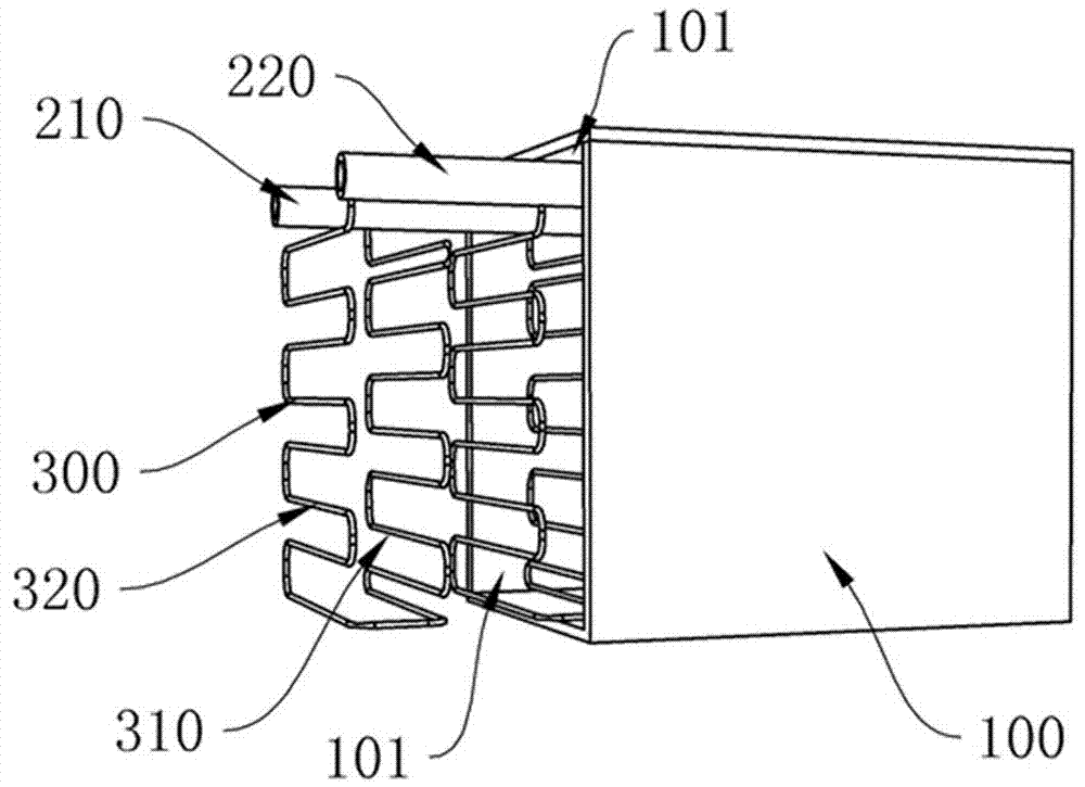
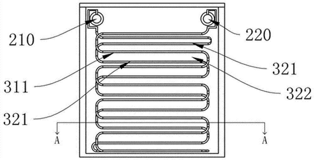
[0025] see Figure 1-Figure 3 , a staggered stacking structure of heat exchange tubes, including inlet headers 220, outlet headers 210, and heat exchange tubes 300, the inlet headers 220, outlet headers 210, and heat exchange tubes 300 are all installed in the housing In the inner cavity 101 of 100, the inner cavity 101 is filled with a phase change material and a pressure relief space is reserved (the entire inner cavity is not filled, and a space is provided for the phase change of the phase change material to reduce the impact of the phase change material on heat transfer tube stress);

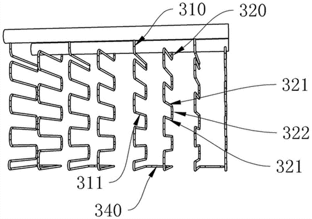
[0026] There are multiple heat exchange tubes, which are evenly distributed in the axial direction of the inlet header 220 and the outlet header 210 .

[0027] The heat exchange tube 300 includes a descending portion 310 and an ascending portion 320, and the descending p...


PUM


Abstract

The invention discloses a staggered stacking structure for heat exchange pipes. The staggered stacking structure comprises an inlet header, an outlet header and the heat exchange pipes, all of which are arranged in an inner cavity of a shell. The inner cavity is filled with phase change materials. The multiple heat exchange pipes are arranged and evenly distributed in the axial direction of the inlet header and the outlet header. By means of the staggered stacking structure, the inlet and outlet direction of the heat charging and heat releasing process is consistent, and local stress caused by contraction or expansion of phase change materials in the heat charging and releasing process is effectively avoided. Meanwhile, the temperature field of a whole phase change energy storage device can be homogenized, the average temperature of transverse sections of different heights in the device is almost consistent, and accordingly the phase change energy storage device can have a better thermodynamic property and more accurate temperature control level.

Description

technical field [0001] The invention relates to a phase change energy storage device of a phase change material, in particular to a staggered superposition structure of heat exchange tubes. Background technique [0002] A phase change energy storage device is a device used to contain phase change materials and store energy through phase change materials. Its conventional structure is to fill the phase change energy storage device with phase edge materials, and then store them in the phase change energy storage device. The heat exchange tube is arranged, generally there is only one heat exchange tube, the external fluid enters the heat exchange tube and enters from the heat exchange tube inlet, flows through the complete heat exchange tube installed in the phase change energy storage device, and then discharges from the heat exchange tube outlet. This structure has the following disadvantages: [0003] 1. When charging, the phase change material will expand from solid to liq...

Claims


Application Information

Patent Timeline
Patent Type & Authority Applications(China)
IPC IPC(8): F28D20/02
CPCF28D20/021Y02E60/14
Inventor 张超申雁鸣汪慰军
Owner 贺迈新能源科技(上海)有限公司
Why Eureka
Try Eureka