
Reliability test method for linear rolling guideway pair

A linear guide pair, accelerated test technology, applied in the testing of mechanical parts, the testing of machine/structural parts, instruments, etc., can solve the problems of shortening the test time, lack of pertinence, general indicators, etc., to solve the problem of long test time , The measurement results are real and effective, and the effect of improving the test efficiency

Inactive Publication Date: 2017-12-22
NANJING UNIV OF SCI & TECH
View PDF4 Cites 3 Cited by
  • Summary
  • Abstract
  • Description
  • Claims
  • Application Information

AI Technical Summary

Problems solved by technology

The mean time between failures (MTBF) of the reliability index of high-end CNC machine tools has reached thousands of hours. According to the traditional test technology to test the rolling linear guide pair, it takes months or even years to put in a test sample. The test can only be completed, and when multiple test samples are invested, the high sample cost is also unbearable
Therefore, the traditional reliability test method can no longer meet the requirements of the rolling linear guide pair, and the accelerated reliability test technology that increases the stress and shortens the test time has become an inevitable trend in the development of reliability test verification technology.
[0003] At present, the domestic research on the reliability test method of rolling linear guides is in a blank state, lacking the corresponding reliability index system of rolling linear guides, and the reliability problems of related rolling linear guides cannot be answered completely and accurately before the products of various manufacturers leave the factory. The performance is that the five elements for the definition of product reliability are not given exactly, the indicators are general, lack of pertinence, and quantitative assessment cannot be carried out

Method used


Image

  • Reliability test method for linear rolling guideway pair
  • Reliability test method for linear rolling guideway pair
  • Reliability test method for linear rolling guideway pair

Examples


Embodiment

[0042] The double stress reliability accelerated test method of rolling linear guide pair includes the following contents:

[0043] 1. Determine the MMBF of the rolling linear guide pair:

[0044] Table 1 The time taken by the corresponding machinery on an assembly line to complete a specific process

[0045] Speed(m / min)

time (min)

4

5

8

4

16

3

0 (product transmission interval time)

0.3

[0046] Calculated according to the assembly line mechanical MTBF = 4000 hours, the mileage of the corresponding rolling linear guide pair is at least:

[0047]

[0048] Table 1 shows the time taken by the corresponding machinery on an assembly line to complete a specific process. Through the analysis of the above typical cases, it can be seen that: in the case of assembly line machinery MTBF = 4000 hours, the corresponding guide rail mileage is 721 kilometers. The reliability measurement test of the rolling linear guide pair needs ...


PUM


Abstract

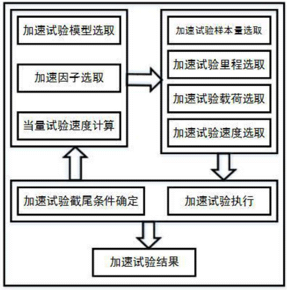
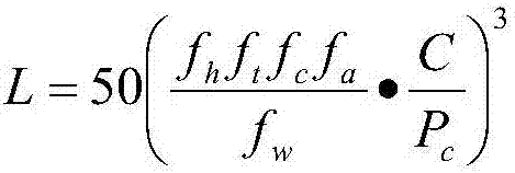
The invention discloses a reliability test method for a linear rolling guideway pair. According to the method, the reliability of a linear rolling guideway pair is evaluated by using an average fault spacing mileage evaluation method; reliability modeling is carried out on a guideway pair by using a reliability acceleration model; a mileage, a load, a speed and a sample size of the test are determined based on a small-sample timing truncation dual-stress reliability test method; on the basis of a guideway pair service life calculation formula, a stress acceleration factor and an equivalent acceleration test speed of the test are calculated and reasonability of a test condition is checked; and then reliability acceleration testing is carried out on the guideway pair by using the determined test condition. The invention aims at providing dual-stress-acceleration-failure-model-based reliability test method for a linear rolling guideway pair, so that problems of too long time, too high cost, and insufficient samplings and the like of the existing linear rolling guideway pair reliability test method are solved and the test efficiency is improved.

Description

technical field [0001] The invention belongs to the field of reliability design test, in particular to a reliability acceleration test method of a rolling linear guide pair. Background technique [0002] Rolling linear guides are the core functional components of CNC machine tools, and the reliability of rolling linear guides will directly affect the reliability of the entire CNC system. The mean time between failures (MTBF) of the reliability index of high-end CNC machine tools has reached thousands of hours. According to the traditional test technology to test the rolling linear guide pair, it takes months or even years to put in a test sample. The test can only be completed, and when multiple test samples are invested, the high sample cost is also unbearable. Therefore, the traditional reliability test method can no longer meet the requirements of the rolling linear guide pair, and the accelerated reliability test technology that increases the stress and shortens the tes...

Claims


Application Information

Patent Timeline
Patent Type & Authority Applications(China)
IPC IPC(8): G01M13/00
CPCG01M13/00
Inventor 欧屹顾旻杰徐阳阳王禹林
Owner NANJING UNIV OF SCI & TECH
Learn More