

Quick pit-digging, tree-digging and transplanting device and method
A fast, blade technology, applied in planting methods, excavation/covering of trenches, agriculture, etc., can solve the problems of tree diggers not adapting to national conditions and markets, unable to unearth soil balls, and difficult to retain root soil, etc. Promote the application value, simple and convenient use, and improve the effect of water utilization
- Summary
- Abstract
- Description
- Claims
- Application Information
AI Technical Summary
Problems solved by technology
Method used
Image


Examples
Embodiment 1
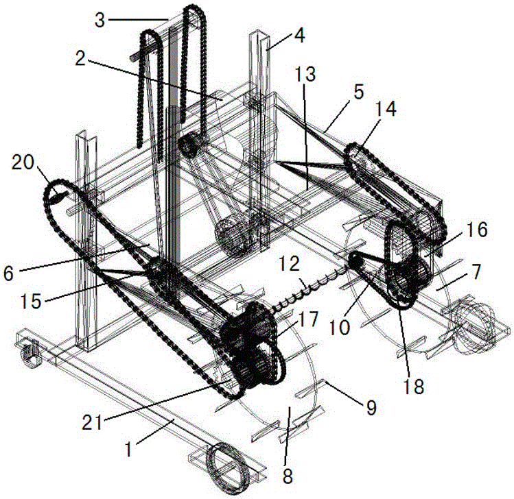
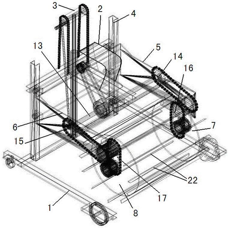
[0038] Embodiment 1, with reference to attached figure 1 , figure 2 , image 3 , Figure 4 , Figure 5 The fast digging and tree transplanting device mentioned in the present invention comprises a walking chassis 1, the tree digging device is connected with the walking chassis 1 through a slide rail 4, and the slide rail 4 realizes the lifting of the tree digging device through a lifter 3, and the tree digging device Including cross arm Ⅰ5 and cross arm Ⅱ6 and the blade part, the middle part of cross arm Ⅰ5 and cross arm Ⅱ6 is installed with the engine 2 used to drive the tree digging device, and the cross arm Ⅰ5 and cross arm Ⅱ6 are installed with vertical cross supports The blade carrying wheel I7 and the blade carrying wheel II8 of the arm are respectively equipped with a rotary knife rocker arm I10 and a rotary knife rocker II11 on the blade carrying wheel I7 and the blade carrying wheel II8, and the blade carrying wheel I7 and the blade carrying wheel II8 can be chang...
PUM
| Property | Measurement | Unit |
|---|---|---|
| Diameter | aaaaa | aaaaa |
Abstract
Description
Claims
Application Information