Auxiliary device for tin soldering for circuit board

A technology for auxiliary devices and circuit boards, applied in auxiliary devices, assembling printed circuits with electrical components, welding positions, etc., can solve the problems of low soldering efficiency, slow soldering speed, and physical harm.

Inactive Publication Date: 2017-12-29
钟光文
View PDF3 Cites 7 Cited by
  • Summary
  • Abstract
  • Description
  • Claims
  • Application Information

AI Technical Summary

Problems solved by technology

[0006] In order to overcome the disadvantages of manually holding a welding tool for soldering, the soldering tool is heavy, soldering is difficult, the efficiency of soldering is low, the speed of soldering is slow, and irritating gas is generated during soldering, which will hurt the body, the technical problem to be solved by the present invention It is to provide a circuit board soldering auxiliary device with fast soldering speed and high soldering efficiency, which can perform front, rear, left, and right soldering of circuit boards, and can also remove irritating odors.

Method used


Image

  • Auxiliary device for tin soldering for circuit board
  • Auxiliary device for tin soldering for circuit board
  • Auxiliary device for tin soldering for circuit board

Examples


Embodiment 1

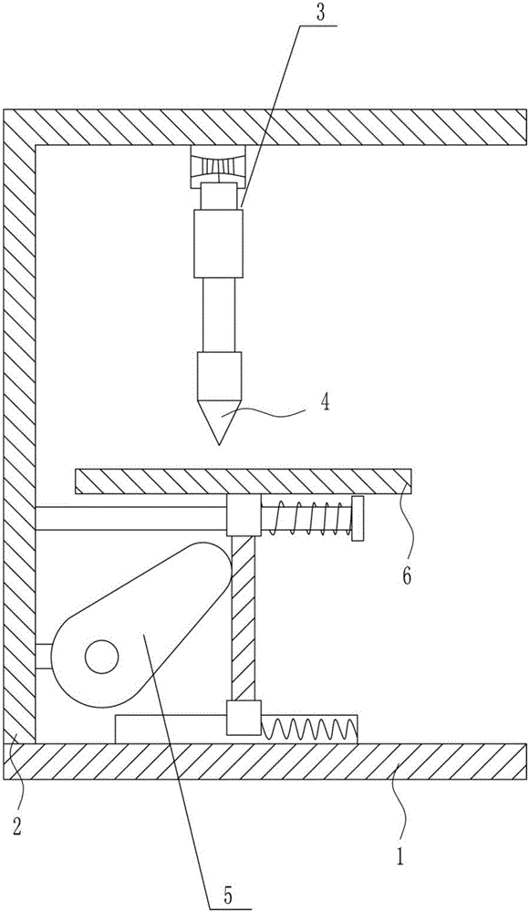
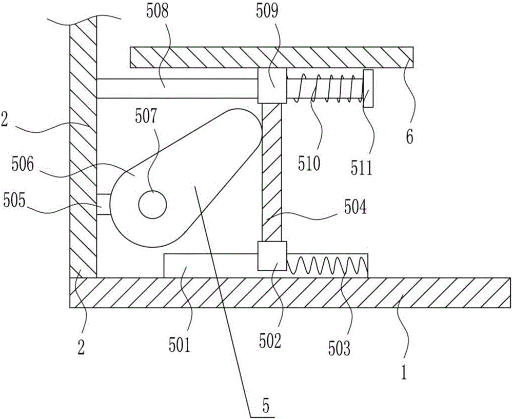
[0040] A circuit board soldering auxiliary device, such as Figure 1-9 As shown, it includes a base plate 1, an L-shaped plate 2, a moving device 3, a soldering iron tip 4, an adjustment device 5, and a placement table 6. The left side of the top of the base plate 1 is provided with an L-shaped plate 2, and the top of the base plate 1 is provided with an adjustment device 5. The top of the adjusting device 5 is provided with a placing platform 6 , the inner top of the L-shaped plate 2 is provided with a moving device 3 , and the bottom of the moving device 3 is provided with a soldering iron tip 4 .

Embodiment 2

[0042] A circuit board soldering auxiliary device, such as Figure 1-9 As shown, it includes a base plate 1, an L-shaped plate 2, a moving device 3, a soldering iron tip 4, an adjustment device 5, and a placement table 6. The left side of the top of the base plate 1 is provided with an L-shaped plate 2, and the top of the base plate 1 is provided with an adjustment device 5. The top of the adjusting device 5 is provided with a placing platform 6 , the inner top of the L-shaped plate 2 is provided with a moving device 3 , and the bottom of the moving device 3 is provided with a soldering iron tip 4 .

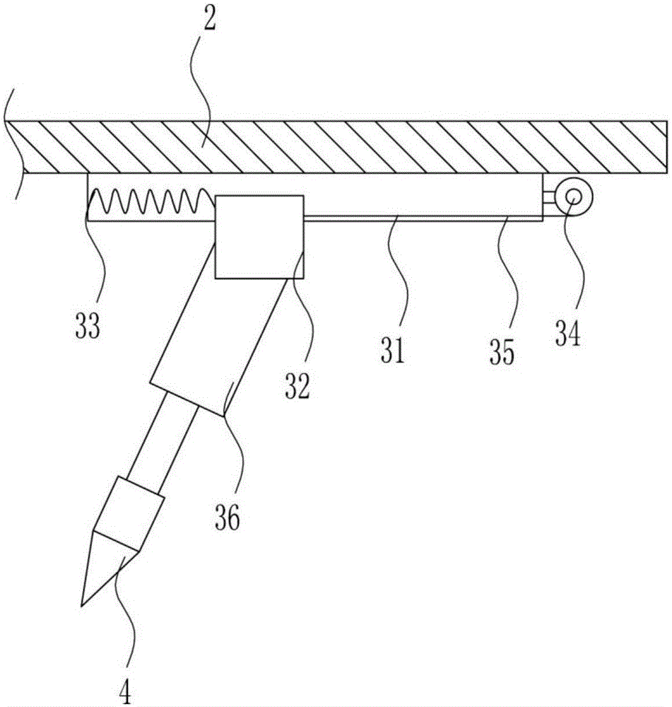
[0043] Mobile device 3 comprises the first slide rail 31, the first slide block 32, the first spring 33, the first electric reel 34, the first backguy 35 and the first electric push rod 36, and the inner top of L-shaped plate 2 is provided with A first slide rail 31 is arranged, and a first slide block 32 is slidably provided on the first slide rail 31. A first spring 33 is conne...

Embodiment 3

[0045] A circuit board soldering auxiliary device, such as Figure 1-9 As shown, it includes a base plate 1, an L-shaped plate 2, a moving device 3, a soldering iron tip 4, an adjustment device 5, and a placement table 6. The left side of the top of the base plate 1 is provided with an L-shaped plate 2, and the top of the base plate 1 is provided with an adjustment device 5. The top of the adjusting device 5 is provided with a placing platform 6 , the inner top of the L-shaped plate 2 is provided with a moving device 3 , and the bottom of the moving device 3 is provided with a soldering iron tip 4 .

[0046] Mobile device 3 comprises the first slide rail 31, the first slide block 32, the first spring 33, the first electric reel 34, the first backguy 35 and the first electric push rod 36, and the inner top of L-shaped plate 2 is provided with A first slide rail 31 is arranged, and a first slide block 32 is slidably provided on the first slide rail 31. A first spring 33 is conne...


PUM


Abstract

The invention relates to an auxiliary device for tin soldering, and particularly relates to an auxiliary device for tin soldering for a circuit board. The technical problem to be solved by the invention is to provide an auxiliary device for tin soldering for a circuit board, which is high in tin soldering speed, high in tin soldering efficiency, capable of carrying out front-rear tin soldering and left-right tin soldering on the circuit board, and further capable of removing a pungent odor. In order to solve the abovementioned technical problem, the invention provides an auxiliary device for tin soldering for a circuit board. The auxiliary device comprises a bottom plate and the like, wherein an L-shaped plate is arranged at the left side of the top of the bottom plate; an adjustment device is arranged at the top of the bottom plate; a placement table is arranged at the top of the adjustment device; a movement device is arranged at the inner top of the L-shaped plate; and a soldering bit is arranged at the bottom of the movement device. The auxiliary device disclosed by the invention achieves the effects of being high in tin soldering speed, high in tin soldering efficiency, and capable of removing the pungent odor. According to the device, the front-rear tin soldering is carried out on the circuit board through the movement device, the left-right tin soldering is carried out on the circuit board through the adjustment device, and therefore, tin soldering can be carried out on each orientation of the circuit board, and an odor removal device is capable of absorbing the pungent odor.

Description

technical field [0001] The invention relates to a soldering auxiliary device, in particular to a circuit board soldering auxiliary device. Background technique [0002] The names of the circuit boards are: ceramic circuit board, alumina ceramic circuit board, aluminum nitride ceramic circuit board, circuit board, PCB board, aluminum substrate, high frequency board, thick copper board, impedance board, PCB, ultra-thin circuit board, ultra-thin Thin circuit boards, printed (copper etching technology) circuit boards, etc. The circuit board makes the circuit miniaturized and intuitive, and plays an important role in mass production of fixed circuits and optimizing the layout of electrical appliances. The circuit board can be called a printed circuit board or a printed circuit board. The birth and development of the rigid-flex board FPC and PCB have given birth to the new product of the rigid-flex board. Therefore, the soft and hard combination board is the flexible circuit boa...

Claims


Application Information

Patent Timeline
Patent Type & Authority Applications(China)
IPC IPC(8): B23K3/00B23K3/02B23K3/08H05K3/34
CPCB23K3/00B23K3/026B23K3/08H05K3/34
Inventor 钟光文胡柳芳纪淑平
Owner 钟光文
Why Eureka
Try Eureka