Pipeline cutting and holing fixture and holing process

A pipe cutting and tooling technology, which is applied in the direction of manufacturing tools, metal processing equipment, welding equipment, etc., can solve the problems of lack of cutting angle displacement, inconvenient movement, and lack of cutting, opening and marking functions, etc., so as to save lifting equipment Works in Taiwan, easy to store and carry, and the effect of eliminating potential safety hazards

Inactive Publication Date: 2017-12-29
MCC BAOSTEEL TECH SERVICE
View PDF8 Cites 18 Cited by
  • Summary
  • Abstract
  • Description
  • Claims
  • Application Information

AI Technical Summary

Problems solved by technology

However, there are three disadvantages in this cutting device: first, the device is a fixed station, the workpiece is located on a fixed tire frame, and the working arm is a single cantilever type, which is inconvenient to move as a whole; Angle displacement, can only cut holes at vertical angles; third aspect, does not have the function of marking lines before cutting holes

Method used


Image

  • Pipeline cutting and holing fixture and holing process
  • Pipeline cutting and holing fixture and holing process
  • Pipeline cutting and holing fixture and holing process

Examples


Embodiment Construction

[0058] The implementation of the present invention will be illustrated by specific specific examples below, and those skilled in the art can easily understand other advantages and effects of the present invention from the contents disclosed in this specification.

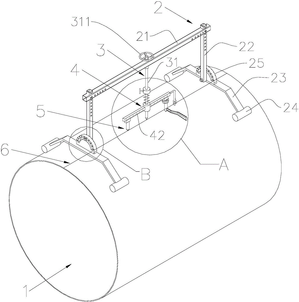
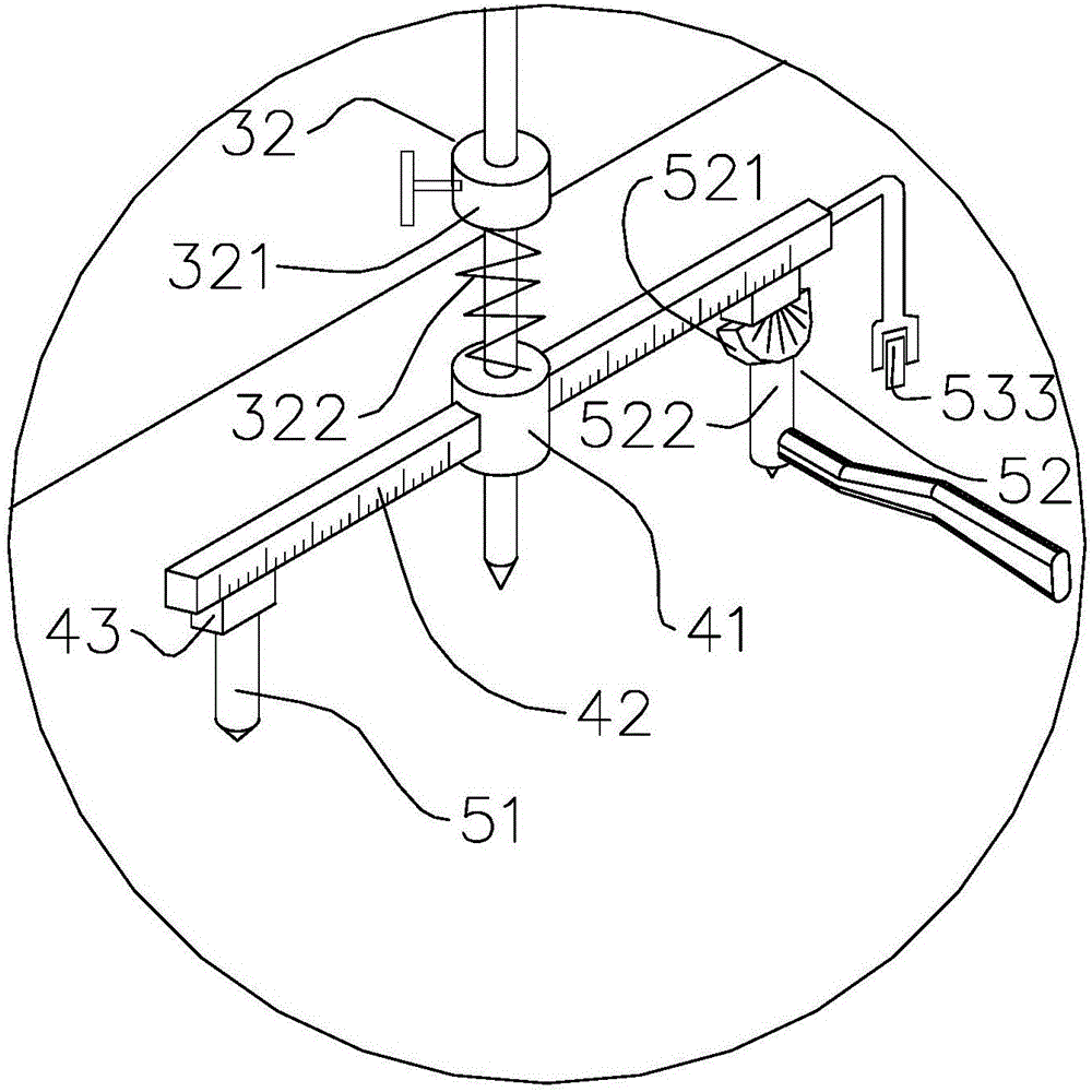
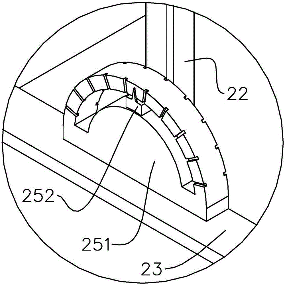
[0059] see Figure 1 to Figure 4 . It should be noted that the structures, proportions, sizes, etc. shown in the drawings attached to this specification are only used to match the content disclosed in the specification, for those who are familiar with this technology to understand and read, and are not used to limit the implementation of the present invention. Limiting conditions, so there is no technical substantive meaning, any modification of structure, change of proportional relationship or adjustment of size, without affecting the effect and purpose of the present invention, should still fall within the scope of the present invention. within the scope covered by the disclosed technical content. At the same ti...


PUM


Abstract

The invention provides a pipeline cutting and holing fixture and a holing process. The pipeline cutting and holing fixture comprises a frame mechanism crossing a pipeline, a centering mechanism used for locating the central point of an intersecting hole, a rotation mechanism and a cutting head, wherein the centering mechanism comprises a rotary lead screw which is vertically arranged, arranged on the frame mechanism in a penetrating manner, and capable of lifting up and down; the rotation mechanism comprises a rotary arm, and the rotary arm is transversally arranged and sleeves the rotary lead screw; and the cutting head is installed on the rotary arm, and driven to carry out intersecting line movement on the outer circumferential wall of the pipeline during rotation. According to the pipeline cutting and holing fixture and the holing process, a station has no need to be fixed, the operation of detachment, movement and cutting can be carried out at any time only by enabling the frame mechanism to cross the outer circumferential wall of the pipeline; the pipeline cutting and holing fixture is simple and convenient to operate, and high in applicability; and moreover, the cost of machining the intersecting hole is lowered.

Description

technical field [0001] The invention relates to a pipeline construction device, in particular to a pipeline cutting and drilling tool and a drilling process. Background technique [0002] Large-diameter engineering pipes are usually welded pipes. The usual manufacturing process is: after the material layout, the CNC cutting machine is used to cut the material, and then the plate is rolled into a cylindrical shape, and finally the circular weld and the straight weld are welded. However, since the outer peripheral wall of the main pipe used for welding the branch pipe is a circular arc surface, the intersecting line between the branch pipe and the main pipe is saddle-shaped, and the intersecting holes on the main pipe cannot be opened on the CNC cutting machine in advance. In addition, due to the large diameter of the main pipe, the usual pipe intersecting wire cutting machine cannot directly drill holes on the surface of the main pipe. [0003] Therefore, the traditional ope...

Claims


Application Information

Patent Timeline
Patent Type & Authority Applications(China)
IPC IPC(8): B23K7/00B23K7/10
CPCB23K7/00B23K7/10
Inventor 陈浩
Owner MCC BAOSTEEL TECH SERVICE
Why Eureka
Try Eureka