
Container type movable charging system

A mobile charging, container-type technology, applied in charging stations for mobile devices, electric vehicle charging technology, charging stations, etc., can solve the problems of immobility, limited number of stations, and large area of ​​charging stations, and achieve installation and commissioning Convenience, high degree of automation, and the effect of saving operating costs

Pending Publication Date: 2017-12-29
力帆科技(集团)股份有限公司
View PDF5 Cites 3 Cited by
  • Summary
  • Abstract
  • Description
  • Claims
  • Application Information

AI Technical Summary

Problems solved by technology

[0003] At present, there are charging stations in the form of charging piles, and there are also charging stations in the form of battery replacement. The charging station in the form of charging piles covers a large area, requires a huge investment, and takes a long time to charge, making it inconvenient for users to use; while charging stations in the form of battery replacement can be used Easy to change at any time, convenient and user-friendly
[0004] The housing of the traditional charging station is constructed manually on the ground, which has a high degree of land transformation, and the way of constructing the housing is cumbersome, and the construction period is long, the construction cost is high, and the traditional charging station occupies a large area. It is difficult to find a suitable site in a bustling area. Therefore, the number of stations to be built is greatly limited, and the location of traditional charging stations is relatively fixed and cannot be moved. The service range is not large, and equipment installation and commissioning are not convenient.

Method used


Image

  • Container type movable charging system
  • Container type movable charging system
  • Container type movable charging system

Examples


Embodiment Construction

[0042] The present invention will be described in detail below in conjunction with the accompanying drawings and specific embodiments.

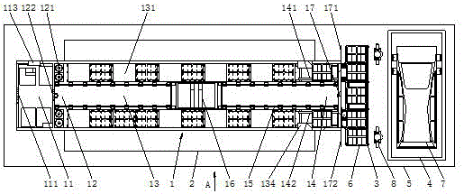
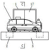
[0043] Such as figure 1 As shown, the container-type mobile charging system of this embodiment includes a movable rectangular parallelepiped housing body 1, and an operation monitoring area 11, a fire-fighting equipment storage area 12, and a charging area are arranged in sequence from one end to the other end in the length direction of the housing body 1. Area 13 and charging tray transfer area 14; the operation monitoring area 11 and the fire fighting equipment storage area 12 are separated by a fire door 122, and the fire fighting equipment storage area 12, charging area 13 and charging tray transfer area 14 are connected; The tray 6 enters and exits the room 1 in the charging tray transfer area 14; a stacker 16 is provided in the charging area 13 and the charging tray transfer area 14 to transfer the charging tray 6 between the charging a...


PUM


Abstract

The invention discloses a container type movable charging system. The container type movable charging system comprises a movable house body, wherein the house body is cuboid; an operation monitoring region, a fire fighting equipment storage region, a charging region and a charging tray transferring region are successively arranged in the house body in the length direction of the house body from one end to the other end; the operation monitoring region is separated from the fire fighting equipment storage region through a fireproof door; the fire fighting equipment storage region and the charging region communicate with the charging tray transferring region; charging trays are transferred in or out of the house body at the charging tray transferring region; the charging region and the charging tray transferring region are respectively provided with stacking machines to transfer charging trays between the charging region and the charging tray transferring regions. The container type movable charging system is small in floor area, low in degree for land reclamation, short in construction cycle, low in construction cost, and convenient to transport, mount and debug.

Description

technical field [0001] The invention relates to a car battery charging device, in particular to a container-type movable charging system. Background technique [0002] At present, electric vehicles and electric construction machinery are more and more applied to our production and life. It is foreseeable that charging stations will be as popular as current gas stations in the future. For this reason, many companies have begun to deploy charging stations and related equipment. . [0003] At present, there are charging stations in the form of charging piles, and there are also charging stations in the form of battery replacement. The charging station in the form of charging piles covers a large area, requires a huge investment, and takes a long time to charge, making it inconvenient for users to use; while charging stations in the form of battery replacement can be used It can be changed at any time, which is convenient and fast, and convenient for users to use. [0004] The...

Claims


Application Information

Patent Timeline
IPC IPC(8): B60L11/18H02J7/00
CPCH02J7/0027B60L53/30B60L53/80Y02T10/70Y02T90/12Y02T10/7072
Inventor 徐旭海吴基富何传祯王安沛曾令唐红梅
Owner 力帆科技(集团)股份有限公司
Learn More