High-power array low-concentration gas pulse combustion method and device

A low-concentration gas and pulsating combustion technology, which is applied in the field of gas combustion, can solve the problems of small output power of a single pulsating combustion device, and achieve the effects of saving investment costs, ensuring stable combustion, and saving industrial sites

Active Publication Date: 2017-12-29
CHINA UNIV OF MINING & TECH +1
View PDF5 Cites 10 Cited by
  • Summary
  • Abstract
  • Description
  • Claims
  • Application Information

AI Technical Summary

Problems solved by technology

[0006] In order to solve the problems of stable pulsating combustion and small output power of a single pulsating combustion device, the present invention provides a method and device for realizing array low-concentration gas pulsating combustion by using a plurality of small pulsating combustion units to form an array

Method used


Image

  • High-power array low-concentration gas pulse combustion method and device
  • High-power array low-concentration gas pulse combustion method and device
  • High-power array low-concentration gas pulse combustion method and device

Examples


Embodiment 1

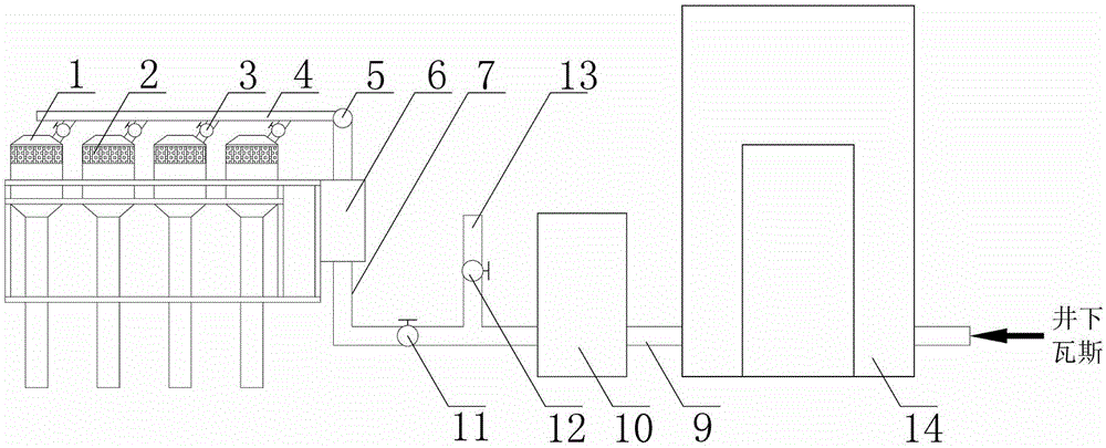
[0046] refer to figure 1 , figure 2 and image 3 In this embodiment, the high-power array type low-concentration gas pulse combustion device is applied to the "fire tube type" energy recovery and utilization method, including the following steps:

[0047] 1. Install the high-power array type low-concentration gas pulsation combustion device 8 on the gas utilization pipeline 9 leading from the coal mine gas drainage pump station 14 .

[0048] 2. Connect the tail of the pulsation combustion unit 1 of the high-power array low-concentration gas pulsation combustion device 8 to one side of the boiler.

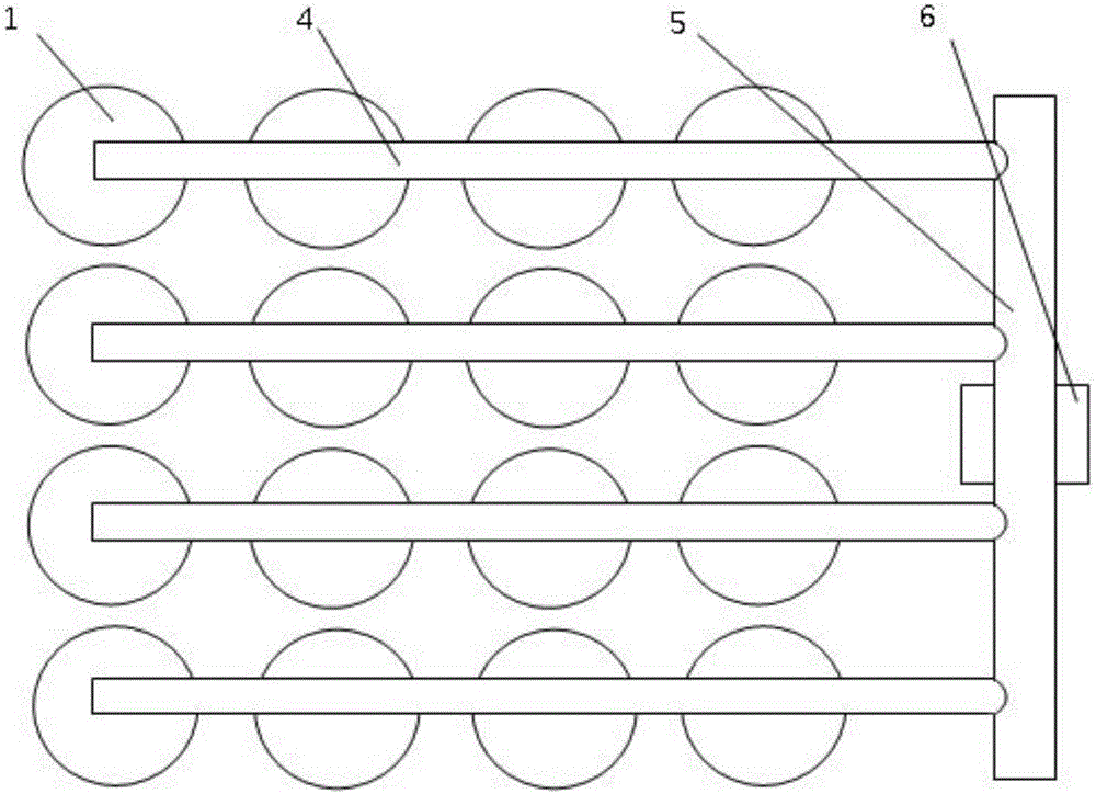
[0049] 3. When working, open the valve 11, the low-concentration gas in the gas utilization pipeline 9 passes through the flame arrester 10, enters the high-power array low-concentration gas pulsating combustion device 8, and passes through the main supply pipe 7 and distribution main pipe 5 in sequence And intake branch pipe 4 enters in the pulse combustion unit 1 to carry out ...

Embodiment 2

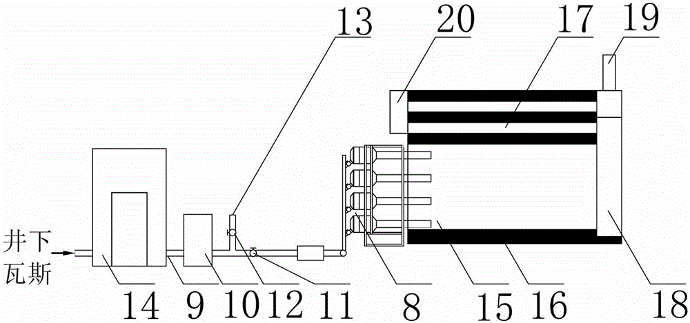
[0052] refer to figure 1 , figure 2 and Figure 4 In this embodiment, the high-power array type low-concentration gas pulse combustion device is applied to the "water pipe type" energy recovery and utilization method, including the following steps:

[0053] 1. Install the high-power array type low-concentration gas pulsation combustion device 8 on the gas utilization pipeline 9 leading from the coal mine gas drainage pump station 14 .

[0054] 2. Connect the tail of the pulsation combustion unit 1 of the high-power array low-concentration gas pulsation combustion device 8 to the bottom of the boiler.

[0055] 3. When working, open the valve 11, the low-concentration gas in the gas utilization pipeline 9 passes through the flame arrester 10, enters the high-power array low-concentration gas pulsating combustion device 8, and passes through the main supply pipe 7 and distribution main pipe 5 in sequence And intake branch pipe 4 enters in the pulse combustion unit 1 to carry ...


PUM


Abstract

The invention belongs to the technical field of gas combustion, and relates to a high-power array low-concentration gas pulse combustion method and a device. 2-16 pulse combustion units with porous medium chambers and damping adjusting valves are arranged to form an independent subarray in an array manner; all units in the subarray share one intake branch pipe; each subarray is connected with a distribution mother pipe through the intake branch pipe to form an array system; and the distribution mother pipe is connected with a supply main pipe with a combustion controller. The porous medium chambers can effectively prevent detonation or explosion; and the damping adjusting valves guarantee balanced intake flows among all the pulse combustion units in the array system. The low-concentration gas utilization range can be narrowed by above 5%, so that the problems of difficult ignition and explosion in the low-concentration gas pulse combustion process are solved, and the stable combustion is guaranteed; and as the number of the pulse combustion units is flexibly combined, the total power of the device can be changed, and low-concentration gas is used more reasonably according to the gas extracting conditions.

Description

technical field [0001] The invention belongs to the technical field of gas combustion, and in particular relates to a high-power array low-concentration gas pulse combustion method and device. Background technique [0002] Gas is an associated resource of coal mines, which is mainly adsorbed on the coal surface in the form of adsorption. With the vigorous mining of coal mines, the gas output has also increased significantly. The gas with a methane concentration greater than 30% can be directly used, but for the gas with a lower concentration, the gas with a concentration greater than 7% is used for gas purification and low concentration. In addition to gas power generation, the gas within 7% is mainly disposed of by emptying, which directly pollutes the environment. [0003] In recent years, in order to make full use of coal mine gas resources, various institutions have increased their investment in research on the combustion and utilization of low-concentration gas, and th...

Claims


Application Information

Patent Timeline
Patent Type & Authority Applications(China)
IPC IPC(8): F23C5/08F23D14/72F23D14/82F23K5/00F23N5/00F22B1/18
CPCF22B1/18F23C5/08F23C2205/10F23D14/72F23D14/82F23K5/005F23K2203/105F23K2400/201F23K2900/05002F23N5/00F23N2237/02
Inventor 袁隆基陈宁娄毅
Owner CHINA UNIV OF MINING & TECH
Why Eureka
Try Eureka