Method for directly generating vortex beam with adjustable order in cavity

A technology of vortex beam and order, applied in the field of laser, can solve the problem of weak ability of order adjustment of vortex beam, and achieve the effect of stable transmission, high purity, and improved ability of order adjustment.

Inactive Publication Date: 2017-12-29
SHANGHAI JIAO TONG UNIV
View PDF4 Cites 10 Cited by
  • Summary
  • Abstract
  • Description
  • Claims
  • Application Information

AI Technical Summary

Problems solved by technology

At present, the method of directly generating vortex beams in the cavity is mainly the ring beam pumping method. However, this method has strict requirements on the intensity distribut

Method used


Image

  • Method for directly generating vortex beam with adjustable order in cavity
  • Method for directly generating vortex beam with adjustable order in cavity
  • Method for directly generating vortex beam with adjustable order in cavity

Examples


Embodiment Construction

[0022] The present invention will be further described in detail below in conjunction with the accompanying drawings.

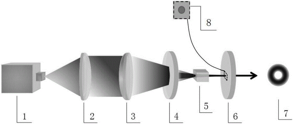
[0023] The method for directly generating an order-adjustable vortex beam in a cavity of the present invention comprises the following steps:

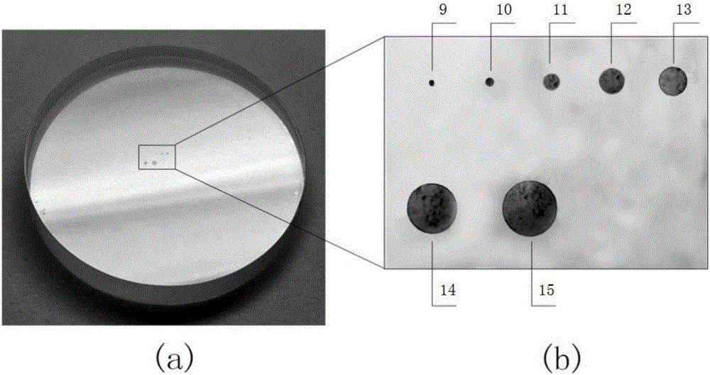
[0024] 1) Build a laser, the laser output end of the laser is engraved with a series of circular micro-holes with different diameters, adjust the laser to output laser;

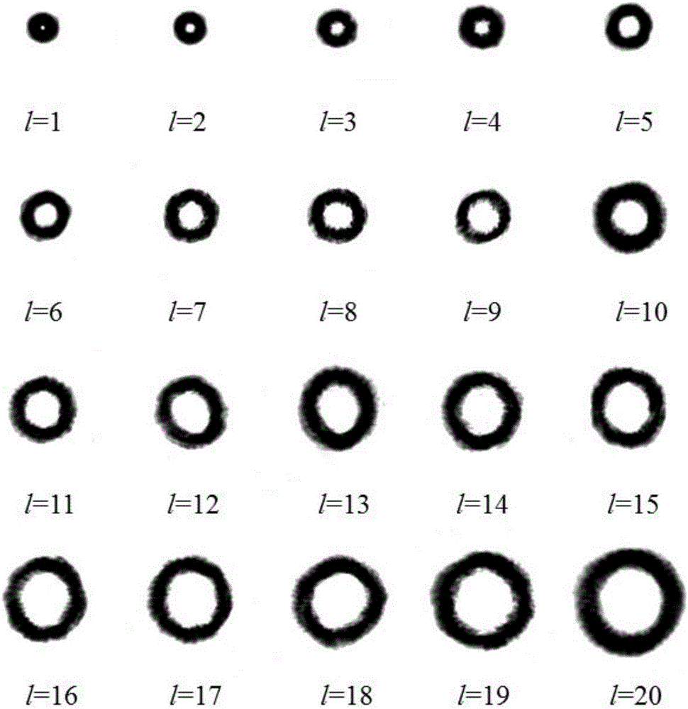
[0025] 2) Install a CCD camera in the laser output direction to monitor the spot pattern of the output laser, adjust the lateral position of the end face, and move a certain circular microhole on the laser output end face to the center of the laser beam until the A circular spot pattern is displayed in the CCD camera, and the generated laser beam has a specific order LG 0l The vortex beam of the mode, wherein l is a non-zero integer, is called the order of the vortex beam;

[0026] 3) Fine-tune the lateral position of the circular microhole or swit...


PUM


Abstract

The invention discloses a method for directly generating a vortex beam with an adjustable order in a cavity, and the core of the method is that a laser output end face of a laser is provided with circular micropores through etching; the circular micropores are adjusted to the center of a laser beam; circular space loss modulation is formed at the center of the laser beam, and the vortex beam with a specific order is enabled to directly oscillate in the cavity and to be outputted. Through the employing of the circular micropores with different diameters and the adjustment of the relative position of the circular micropores and the center of the beam, the method can achieve the continuous adjustment of the order of the vortex beam in a large range, wherein the adjustment range can reach dozens of orders or hundreds of orders. The vortex beam generated through the method is high in purity, and is stable in transmission.

Description

technical field [0001] The invention belongs to the field of laser technology, in particular to a method for directly generating an order-adjustable vortex beam in a cavity. Background technique [0002] The vortex beam has a spiral wavefront phase, and its wavefront phase changes by 2π times around the center, and each photon in the beam carries The orbital angular momentum of , where l is a non-zero integer, is called the topological charge (order) of the vortex beam. The uncertainty of the central phase leads to an intensity singularity in the center, and the light intensity distribution is circular. The above characteristics make vortex beams widely used in quantum communication, optical micro-manipulation, super-resolution imaging, and astronomical observation. [0003] The current method of generating vortex beams is usually to modulate the fundamental mode Gaussian beams outside the cavity, such as spiral phase plates, computational holographic gratings, liquid cry...

Claims


Application Information

Patent Timeline
IPC IPC(8): G02B27/09H01S3/08H01S3/091
CPCG02B27/0927H01S3/08H01S3/08068H01S3/091
Inventor 谢国强乔桢钱列加袁鹏吴雨航
Owner SHANGHAI JIAO TONG UNIV
Why Eureka
Try Eureka