A Cold Cathode Radiation Source Based on Helical Ribbon Electron Injection

A strip electron, cold cathode technology, applied in the fields of submillimeter wave and terahertz electric vacuum devices, microwaves, and millimeter waves, can solve the problems of current on the surface of the medium, reduce the voltage resistance of the device, and spark, and achieve increased Interaction area, stabilization and miniaturization, the effect of increasing the emission area

Active Publication Date: 2019-06-07
UNIV OF ELECTRONICS SCI & TECH OF CHINA
View PDF3 Cites 0 Cited by
  • Summary
  • Abstract
  • Description
  • Claims
  • Application Information

AI Technical Summary

Problems solved by technology

However, it is precisely because of the addition of a specific insulating medium that the medium is relatively thin, on the order of microns, so that it is easy to mix metal shavings or impurities in the manufacturing process, resulting in the presence of current on the surface of the medium, resulting in sparking and damage to the device. Work
At the same time, since the field emission is related to the strength of the surface electric field, the higher the electric field strength, the better in theory. Therefore, there is a very high requirement for the withstand voltage strength of the device, but the introduction of the medium in its structure greatly reduces the performance of the device. voltage resistance, but cannot generate large current
[0006] Therefore, this grid-controlled cold-cathode electron source array with embedded electrodes is not suitable for electric vacuum radiation source devices or devices requiring large currents

Method used


Image

  • A Cold Cathode Radiation Source Based on Helical Ribbon Electron Injection
  • A Cold Cathode Radiation Source Based on Helical Ribbon Electron Injection
  • A Cold Cathode Radiation Source Based on Helical Ribbon Electron Injection

Examples


Embodiment Construction

[0037] In order to make the object, technical solution and advantages of the present invention clearer, the present invention will be further described in detail below in conjunction with the accompanying drawings.

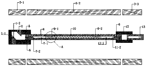
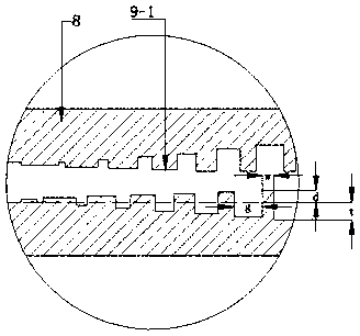
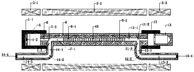
[0038] Such as Figure 1-5 As shown, this implementation case provides a kind of cold cathode radiation source based on spiral ribbon electron injection, which mainly includes spiral ribbon injection electron gun (by cathode block 1-1, cathode emission surface 1-2, anode block 2, electron gun packaging insulator 5), guiding magnetic field 3 (generated by electron gun magnetic field generator 3-1, high-frequency system magnetic field generator 3-2, collector pole magnetic field generator 3-3), periodic structure metal shell 8 and collector pole 13 and other components , the spiral ribbon electron injection cold cathode radiation source system is not filled with medium (it is a vacuum environment). The materials of the cathode emitting surface 1-2 of the electron g...


PUM


Abstract

The invention discloses a cold cathode radiation source based on spiral ribbon electron injection, which relates to the technical field of microwave, millimeter wave, submillimeter wave and terahertz electric vacuum devices, and consists of a cathode block, a cathode emitting surface, an anode block and an electron gun package insulator The spiral ribbon electron injection cold cathode electron gun, periodic structure metal shell, collector, guiding magnetic field generator, the cathode emission surface is rectangular; the lower surface of the anode block is a slope inclined downward to the right, and the anode block is located on the upper right of the cathode block square; the metal shell with periodic structure is provided with electron injection channels that run through the left and right ends of the metal shell with periodic structure, and the middle part of the electron injection channel is provided with a high-frequency structure extending axially along the electron injection channel; the collector, electron injection channel, and cathode emitting surface are located on a straight line. The invention proposes a spiral ribbon-shaped electron injection cold-cathode electron gun with simple structure, long service life and excellent performance, which utilizes the interaction between the longitudinal velocity of the electron injection and the high-frequency field to hand over energy to realize electromagnetic radiation.

Description

technical field [0001] The invention relates to the technical field of microwave, millimeter wave, submillimeter wave and terahertz electric vacuum devices, in particular to a cold cathode radiation source based on spiral ribbon electron injection. Background technique [0002] Field electron emission is a form of electron emission that is completely different in nature from thermionic emission. Thermionic emission is based on raising the temperature of the object, giving additional energy to the electrons inside the object, so that some high-energy electrons can escape over the potential barrier on the surface of the object. The current density that thermionic emission can provide is no more than a few hundred A / cm 2 , and there is still a period of hysteresis; but even if the metal is heated to a high temperature where significant evaporation occurs, the number of electrons that can escape only accounts for a very small part of the number of free electrons in the metal, a...

Claims


Application Information

Patent Timeline
Patent Type & Authority Patents(China)
IPC IPC(8): H01J3/02
CPCH01J3/021H01J3/027
Inventor 袁学松陈青云鄢扬李海龙王彬蒙林
Owner UNIV OF ELECTRONICS SCI & TECH OF CHINA
Why Eureka
Try Eureka